 Z&Z STROTEC
CNC Troubleshooting Guide: Chatter, Poor Finish, Tool Breakage & Positioning Errors
CNC 加工異常排除指南:震刀、表面粗糙、刀具斷裂與定位誤差 · CNC 트러블슈팅 가이드: 채터·거친 표면·공구 파손·위치 오차
View interactive version · 完整互動版 · 인터랙티브 버전 →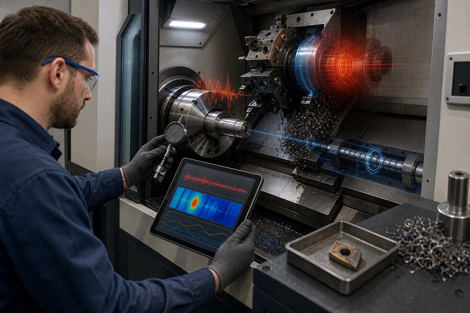
A Failed Part Is Rarely Just the Tool
When a workpiece fails inspection, the problem is seldom the cutting tool alone — it is usually a symptom of micro-vibration, thermal expansion, or poor chip evacuation. Below is a practical guide to diagnosing and solving the most commonly searched CNC machining issues with the right peripheral upgrades.1. Poor Surface Finish & Chatter Marks
A poor surface finish (Ra) or visible chatter marks (震刀痕) is a clear sign of micro-vibration during cutting. Cause: lack of rigidity in the tool setup, or mechanical wear in the machine's axes.- Check your : on a live turret, gear backlash or worn bearings cause chatter. A BMT interface with dynamic balancing and ceramic bearings greatly reduces this vibration.
- Inspect the : if the bed lacks rigidity, vibration transfers to the part. Moving from ball-type to roller-type guides provides the rigidity needed for heavy milling and cleaner finishes.
2. Chip Nesting & Tool Breakage
Especially common in deep-hole drilling or when machining gummy materials like aluminium and low-carbon steel. Chip nesting (鐵屑纏繞) occurs when long, stringy chips wrap around the tool, trapping heat and creating a vapor barrier that standard flood coolant cannot penetrate — ultimately leading to tool breakage (刀具斷裂).- Fix: upgrade to . Pumping coolant through the spindle at up to 70 BAR breaks chips into small pieces, flushes them from the cavity, and pierces the vapor barrier to keep the edge cool — meaningfully extending tool life.
3. Taper After Turning & Thermal Drift
When turning a long cylindrical part, the diameter at the end may differ from the chuck end. Taper (車削錐度) can come from a lack of tailstock support, but in high-speed machining the hidden culprit is often thermal drift (熱變位): as the spindle runs at 10,000+ RPM, heat expands the casting and ball screws, shifting the Z-axis dynamically.- Fix: apply whole-machine thermal compensation via the CNC controller, and equip the spindle with air-oil lubrication and to physically remove heat from the core.
4. Positioning Error & Burr Formation
You program a 10.000 mm move but the machine travels 10.005 mm; or the part comes out with heavy burrs needing manual deburring. Positioning error (定位誤差) usually stems from the drive system failing to follow the controller exactly. Burr formation (毛邊) happens when the tool rubs instead of cuts — often from this micro-positioning lag or tool wear.- Fix: optimize the . A servo with a high-resolution absolute encoder (e.g. Yaskawa's current Sigma-X series or Siemens SINAMICS) gives very fine feedback, reducing following errors and the friction that produces burrs.
Most machining bottlenecks can be resolved by upgrading the right peripherals. From high-pressure CTS units and rigid tool holders to precision linear guides and servo drives, Z&Z STROTEC provides the solutions for lights-out, high-precision manufacturing.
Connected CNC, Hidden Risk: An OT Cybersecurity Procurement Checklist for Machine Tool Buyers
Some of the fastest ways to diagnose a fault — a supplier dialling in, a USB stick carrying a corrected program, an alarm history pulled off the controller — are also the paths an intruder would use. The access that shortens downtime needs boundaries around it.
Remote support genuinely shortens downtime on imported equipment; what creates risk is the always-on, unsupervised channel. Encryption, MFA, per-session approval, time-limited access and a plant-side way to disconnect keep the benefit without the standing exposure.
Alarm history, login records and a trail of parameter changes all answer the same question: what changed before this started? A fault investigation and a security investigation open with it. Check at purchase whether those records can leave the machine.
Live Tool Holder Troubleshooting: Causes of Overheating, Noise, Runout and Coolant Leakage
When chatter marks, oversize holes or repeated tool breakage appear only on driven-tool operations, the fault is usually in the live tool holder rather than in the machine. Narrowing that down is a different sequence from general machine troubleshooting.
Does the noise persist with the cutting load removed; does it change between low and high speed; does it appear in both directions of rotation; does it come from the front end, the drive end or inside the turret; and does it disappear when a known-good holder is fitted in the same station.
Fast temperature rise with a burnt smell, catching or play when the output shaft is turned by hand, visible runout, metallic knocking, coolant that may have reached the bearings, or a holder that has been crashed. Past that point, more machining only extends the damage.
加工不良,往往不只是刀具的問題
當工件檢驗不合格,問題很少只出在切削刀具,而多半是微震動、熱膨脹或排屑不良的症狀。以下彙整幾個最常被搜尋的 CNC 加工問題,說明如何診斷與解決。1. 表面粗糙度不佳與震刀痕
表面粗糙度(Ra)不良或可見的震刀痕(chatter marks),是切削過程中發生微震動的明確訊號。成因:刀具設定剛性不足,或機台軸向機械磨損。- 檢查:動力刀塔的齒輪背隙或軸承磨損會直接引起震刀。升級為具動平衡與陶瓷軸承的 BMT 介面,可大幅降低此類震動。
- 檢查:床台剛性不足時,震動會傳遞到工件。由滾珠式改為滾柱式線軌,可提供重銑削與精密加工所需的剛性。
2. 鐵屑纏繞與刀具異常斷裂
在深孔鑽削,或加工鋁、低碳鋼等黏性材料時特別常見。鐵屑纏繞(chip nesting)是指細長的鐵屑纏繞刀具、蓄積熱量,形成一般冷卻液無法穿透的蒸氣屏障(vapor barrier),最終導致刀具斷裂(tool breakage)。- 解方:升級。以最高 70 BAR 直接透過主軸噴出冷卻液,將鐵屑打斷成小段並沖出孔穴,同時穿透蒸氣屏障、冷卻刃口,有助於明顯延長刀具壽命。
3. 車削產生錐度與熱變位
車削細長圓柱件時,可能發現末端直徑與夾頭端不同。車削錐度(taper)可能源自尾座支撐不足;但在高速加工中,隱藏的元凶常是熱變位(thermal drift)。當主軸以 10,000+ RPM 運轉,發熱使鑄件與滾珠螺桿膨脹,使 Z 軸動態偏移。- 解方:透過 CNC 控制器實施全機熱補償,並讓主軸配備氣油潤滑與 ,從核心實際帶走熱量。
4. 定位誤差與毛邊過多
你指令機台移動 10.000 mm,實際卻走了 10.005 mm;或工件出現需人工去除的重毛邊。定位誤差(positioning error)通常來自驅動系統未能精確跟隨控制器指令;毛邊(burr)則常因這種微定位落後或刀具磨損,使刀具摩擦而非切削所致。- 解方:優化。升級為搭載高解析絕對式編碼器的伺服(如 Yaskawa 現行 Sigma-X 系列、Siemens SINAMICS),可提供極精細的回授,降低跟隨誤差與造成毛邊的摩擦。
多數加工瓶頸,都能靠升級正確的周邊設備來化解。從高壓 CTS、剛性刀座,到精密線性滑軌與伺服驅動,Z&Z STROTEC 提供對應的周邊解決方案,協助您穩定達成高精度加工,並邁向無人化生產(夜間無人看管也能持續運轉的「熄燈工廠」)。
連網 CNC 的隱形風險:工具機買家必備的 OT 資安採購清單
診斷故障最快的幾種方式——請原廠連線進來、用 USB 帶一支修好的程式、把控制器的警報歷史撈出來——同時也是入侵者會走的路徑。能縮短停機的存取方式,需要有邊界。
遠端支援確實能縮短進口設備的停機時間,真正的風險是長期開啟又無人監督的通道。加密連線、MFA、逐次核准、限時權限,加上工廠端可隨時中斷的手段,能保留好處而不留下常態暴露。
警報歷史、登入紀錄與參數變更軌跡,回答的都是同一個問題:開始出狀況之前,到底改了什麼?故障調查與資安調查的第一個問題其實一樣。採購時就該確認這些紀錄能不能離開機台。
動力刀座故障診斷:過熱、異音、偏擺與漏水的原因及處理方式
當震紋、孔徑偏大或刀具反覆斷裂只出現在動力刀具的加工項目上,問題通常在動力刀座,而不是機台本身。要縮小這個範圍,用的順序和一般機台異常排除並不相同。
拆除切削負載後是否仍有異音;低速與高速的聲音是否不同;正轉與反轉是否都出現;聲音來自刀座前端、驅動端還是刀塔內部;換上已知正常的刀座、裝在同一刀位後症狀是否消失。
溫度快速上升並伴隨焦味、手轉輸出軸有卡點或明顯間隙、肉眼可見的偏擺、金屬敲擊聲、冷卻液可能已進入軸承,或刀座曾經撞機。超過這條線之後,繼續加工只會擴大損害。
불량은 공구만의 문제가 아닙니다
가공 불량이 나오면 원인은 절삭 공구 하나가 아닌 경우가 많습니다. 대개 미세 진동, 열팽창, 칩 배출 불량의 증상입니다. 아래는 자주 검색되는 CNC 가공 문제의 진단과 해결 정리입니다.1. 표면이 거칠거나 채터 마크가 보일 때
거친 표면 조도(Ra)나 눈에 보이는 채터 마크(震刀痕)는 절삭 중 미세 진동의 신호입니다. 원인은 공구 세팅의 강성 부족이나 축의 기계적 마모입니다.- 점검: 동력 터릿의 기어 백래시나 베어링 마모는 채터를 유발합니다. 동적 밸런싱과 세라믹 베어링을 갖춘 BMT 인터페이스로 업그레이드하면 진동을 크게 줄일 수 있습니다.
- 점검: 베드 강성이 부족하면 진동이 부품으로 전달됩니다. 볼 타입에서 롤러 타입 가이드로 바꾸면 중절삭과 정밀 가공에 필요한 강성을 확보할 수 있습니다.
2. 칩 엉킴과 공구 파손
심공 드릴링이나 알루미늄·저탄소강 같은 점착성 재료 가공에서 특히 흔합니다. 칩 엉킴(鐵屑纏繞)은 길고 질긴 칩이 공구를 감으면서 열을 가두고, 일반 플러드 절삭유가 뚫지 못하는 증기막(vapor barrier)을 형성해 결국 공구 파손(刀具斷裂)으로 이어집니다.- 해결: 로 업그레이드. 최대 70 BAR로 주축을 통해 절삭유를 분사하면 칩을 잘게 끊어 배출하고 증기막을 뚫어 절삭날을 냉각합니다. 그 결과 공구 수명을 의미 있게 늘릴 수 있습니다.
3. 선삭 테이퍼와 열 변위
긴 원통 부품을 선삭할 때 끝단 지름이 척 쪽과 달라지는 경우입니다. 테이퍼(車削錐度)는 심압대 지지 부족이 원인일 수도 있지만, 고속 가공에서는 숨은 원인이 열 변위(熱變位)인 경우가 많습니다. 주축이 10,000+ RPM으로 돌면 발열로 주물과 볼스크루가 팽창해 Z축이 동적으로 이동합니다.- 해결: CNC 컨트롤러의 전기(全機) 열보정 기능을 활용하고, 주축에 에어-오일 윤활과 를 적용해 코어에서 열을 물리적으로 제거합니다.
4. 위치 오차와 버(burr)
10.000mm를 지령했는데 10.005mm를 이동하거나, 수작업 디버링이 필요한 심한 버가 생기는 경우입니다. 위치 오차(定位誤差)는 대개 구동계가 지령을 정확히 따르지 못해 발생하고, 버(毛邊)는 이 미세 지연이나 공구 마모로 공구가 절삭 대신 문지를 때 생깁니다.- 해결: 최적화. 고분해능 앱솔루트 엔코더를 갖춘 서보(예: Yaskawa 현행 Sigma-X 시리즈, Siemens SINAMICS)는 매우 정밀한 피드백을 제공해 추종 오차를 줄이고 버를 유발하는 마찰을 낮춥니다.
대부분의 가공 병목은 알맞은 주변장치 업그레이드로 해결됩니다. 고압 CTS, 강성 높은 공구대, 정밀 리니어 가이드, 서보 드라이브까지 Z&Z STROTEC가 대응 솔루션을 제안하여, 안정적인 고정밀 가공과 무인 운전(야간 무인 가동, 라이트아웃 공장)을 실현하도록 돕습니다.
네트워크에 연결된 CNC의 보이지 않는 위험: 공작기계 구매자를 위한 OT 사이버 보안 체크리스트
고장을 가장 빨리 파악하는 방법들 — 공급사의 원격 접속, 수정된 프로그램을 담은 USB, 제어기에서 추출한 알람 이력 — 은 침입자가 이용하는 경로이기도 합니다. 정지 시간을 줄여 주는 접근에는 경계가 필요합니다.
원격 지원은 수입 설비의 정지 시간을 실제로 줄여 줍니다. 위험을 만드는 것은 상시 개방된 무감독 통로입니다. 암호화, MFA, 건별 승인, 시간 제한 권한, 공장 측 차단 수단을 갖추면 이점은 유지하면서 상시 노출은 없앨 수 있습니다.
알람 이력, 로그인 기록, 파라미터 변경 이력은 모두 같은 질문에 답합니다. 문제가 시작되기 전에 무엇이 바뀌었는가. 고장 조사와 보안 조사가 똑같이 던지는 첫 질문입니다. 이 기록을 장비 밖으로 내보낼 수 있는지 구매 시 확인하십시오.
라이브 툴 홀더 고장 진단: 과열·이음·런아웃·절삭유 누유의 원인과 대처
채터 자국, 구멍 치수 초과, 반복적인 공구 파손이 동력 공구 가공에서만 나타난다면 원인은 기계가 아니라 라이브 툴 홀더인 경우가 많습니다. 이를 좁혀 가는 순서는 일반적인 기계 이상 진단과 다릅니다.
절삭 부하를 없애도 이음이 남는가, 저속과 고속에서 소리가 다른가, 정회전과 역회전 모두에서 나타나는가, 소리가 홀더 앞단·구동단·터렛 내부 중 어디에서 오는가, 정상으로 확인된 홀더를 같은 공구 위치에 장착하면 증상이 사라지는가.
탄 냄새를 동반한 급격한 온도 상승, 손으로 출력축을 돌릴 때의 걸림이나 뚜렷한 유격, 육안으로 보이는 흔들림, 금속성 타격음, 베어링까지 들어갔을 수 있는 절삭유, 충돌 이력. 이 선을 넘은 뒤의 가공은 손상만 키웁니다.
장비 모델명, 부품 번호 또는 현장 사진을 보내주시면 공급 가능 여부와 가격을 회신드립니다.
Multi-brand selection rather than one factory, spec and compatibility checks in writing, a test cut and inspection at the plant before the machine ships, export documentation, and the same part number still available years later. Installation and after-sales in Korea, Brazil, Switzerland and Argentina run through local agents; for other markets we supply parts and components.
不綁單一工廠的多品牌選型、白紙黑字的規格與相容性確認、出貨前在工廠端試車驗機、出口文件,以及數年後仍拿得到的同一料號。韓國、巴西、瑞士、阿根廷的安裝與售後由在地服務商執行,其他市場我們供應零件與零組件。
단일 공장에 묶이지 않는 다중 브랜드 선정, 문서로 남기는 사양·호환성 확인, 선적 전 공장 시운전과 검사, 수출 서류, 그리고 수년 뒤에도 확보 가능한 동일 품번. 한국·브라질·스위스·아르헨티나의 설치와 애프터서비스는 현지 대리점이 담당하며, 그 외 시장에는 부품을 공급합니다.