 Z&Z STROTEC
CNC Spindle Selection, Acceptance Testing and Troubleshooting
CNC 主軸選型、驗收與故障診斷指南 · CNC 주축 선정·검수·고장 진단 가이드
View interactive version · 完整互動版 · 인터랙티브 버전 →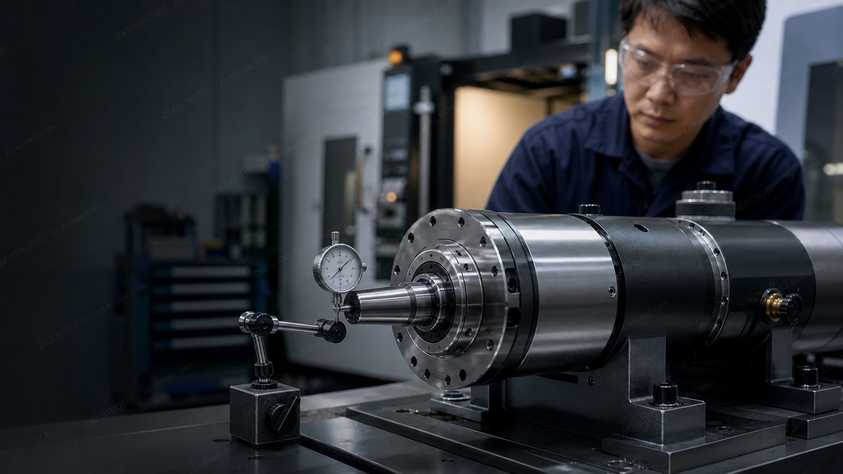
Maximum RPM Is Not the Whole Specification
The spindle directly affects machining capability, surface finish, tool life and the risk of unplanned downtime. Comparing only maximum speed and motor power can overlook the factors that decide real cutting performance: the torque curve, base speed, tooling interface, bearing arrangement, lubrication and cooling.
A spindle built for high-speed aluminium or mould work will not necessarily suit heavy steel cutting, and a spindle with generous low-speed torque will not necessarily suit long runs at very high speed. Selection should start from the workpiece, the tool and the cutting process rather than from a chosen maximum RPM.
1. Information Required for Spindle Selection
1.1 Material and operation
- Aluminium, small-diameter tools and finishing work usually favour high-speed capability.
- Steel, stainless steel and larger tools generally need more low-speed torque.
- Drilling, tapping, heavy roughing and high-speed contouring make different demands on the spindle.
- A lathe spindle also has to be checked against bar diameter, spindle bore, chuck and draw-tube dimensions.
1.2 Power, torque and base speed
Rated power on a datasheet does not represent cutting capability on its own. Ask for:
- Continuous and short-time power
- Continuous and short-time torque
- Base speed
- Constant-torque and constant-power ranges
- Power and torque available at the speed you will actually cut at
Two spindles carrying the same stated power can behave very differently in low-speed heavy cutting, because base speed and drive arrangement differ.
1.3 Drive arrangement
- Belt-driven: a mature arrangement, relatively easy to service, and speed and torque can be adjusted through the pulley ratio. Belt tension, wear and balance all show up as vibration.
- Direct-coupled: the motor drives the spindle directly, with fewer transmission parts, and suits medium to high speeds. Coupling accuracy and alignment matter a great deal.
- Built-in motor: the motor is integrated into the spindle, suiting high speed and rapid acceleration, but placing higher demands on cooling, bearings, lubrication and service capability.
- Geared: gives higher low-speed torque for heavy cutting, at the cost of gear noise, lubrication requirements and backlash.
No single arrangement is best in every condition. The choice follows material, tool diameter, cutting load and the expected speed range.
1.4 Tooling interface
BT, BBT, CAT, HSK and polygonal taper interfaces differ in contact method, rigidity, high-speed behaviour and tool-change system. Confirming the interface also means confirming:
- Taper form and size
- Pull stud or clamping mechanism
- Spindle drawbar force
- Whether tooling has to be balanced
- Compatibility with the existing magazine and holders
- Coolant-through-spindle pressure and sealing
A matching interface name does not mean every holder, pull stud or tool-change component is interchangeable.
1.5 Bearings, preload and lubrication
Machine-tool spindles commonly use precision angular contact ball bearings, sometimes combined with cylindrical roller bearings, to reach the required radial rigidity, axial load capacity and speed capability.
Preload raises rigidity and running accuracy, but preload, speed, load and temperature are linked. Excessive operating preload increases friction and temperature rise, so maximum rigidity is not the goal on its own.
Grease and oil-air lubrication are both common. A high-speed oil-air system has to deliver a small, metered oil quantity consistently; too little, too much, the wrong oil or contamination can all produce abnormal temperature rise and bearing damage.
1.6 Manufacturing accuracy and dynamic balancing
A high-quality spindle depends on more than precision bearings. Its shaft, taper, bearing seats and mating surfaces require precision machining and grinding to control roundness, concentricity, face squareness and fit. Geometric errors in these features show up in spindle runout, bearing loading and tool-change repeatability.
After assembly, the rotating components and the complete spindle assembly are normally dynamically or trim balanced for their design speed. Balancing corrects uneven mass distribution and couple unbalance, reducing centrifugal force, vibration, bearing load and surface marking at high speed.
A balanced spindle does not make every tool assembly fit for high-speed use. The holder, collet, cutting tool, pull stud and retained coolant form a second rotating system. Where the spindle and tooling manufacturers require it, the complete tool assembly should be balanced and its overhang controlled.
2. Acceptance Checks for a New or Replaced Spindle
A spindle should not be accepted simply because it turns without an alarm. Record the following under test conditions agreed in advance.
2.1 Visual and system checks
- Spindle nameplate, model and serial number
- Tooling interface and pull-stud specification
- Lubricant, coolant and air-supply conditions
- Hoses, fittings and seals checked for leakage
- Encoder, orientation and tool-change functions
- Chiller setpoint against actual temperature
2.2 Spindle runout
Use a calibrated test arbor and indicator to measure radial runout near the spindle nose and at an agreed projection. The report should record at least:
- Arbor specification and calibration status
- Measurement position and projection length
- Whether the spindle was cold or warmed up
- Measurement method and instrument resolution
- Measured result and acceptance limit
Measured runout can include error from the spindle, the taper, the arbor, the holder, the clamping and the measuring setup, so results only compare when the method is held constant.
2.3 Temperature rise, thermal displacement and compensation
As a spindle runs from cold to thermal stability, the bearings, motor and spindle head deform. Following the manufacturer's procedure, raise speed in stages and record:
- Temperature at the spindle nose or a specified point
- Coolant inlet and outlet temperature
- Speed and duration at each stage
- Axial or radial thermal displacement
- Time taken to reach a stable condition
Modern machine tools do not rely on warm-up alone to manage thermal deformation. Depending on the machine, spindle cooling and oil-air lubrication are combined with thermally balanced structural design, temperature sensors and CNC thermal-error compensation. Using spindle speed, running time and measured machine or ambient temperature, the control can estimate thermal displacement and correct axis position.
Compensation does not replace correct lubrication, cooling or warm-up. Cooling controls heat generation and temperature distribution; compensation corrects the predictable displacement that remains. A chiller failure, a faulty sensor or a thermal condition outside the compensation model can still produce unacceptable dimensional error on a machine that has the function.
When accepting a machine with thermal compensation, confirm:
- Which temperature and operating data the compensation uses
- When compensation becomes active, and whether it can be monitored
- Actual dimensional change from a cold start to thermal stability
- Whether spindle replacement or machine recalibration requires new compensation data
- The test conditions used with compensation enabled and disabled
There is no universal normal temperature or compensation value for every spindle. Ambient temperature, speed, bearings, lubrication, cooling, sensor position and machine structure all change the result, so judgement rests on the manufacturer's specification for that model and baseline data taken under comparable conditions.
2.4 Vibration and abnormal noise
A vibration measurement has to record the measuring point, sensor direction, mounting method, speed, the tool or arbor fitted, and the frequency band. A single overall vibration value is rarely enough to diagnose a fault on its own.
ISO 20816-1 sets out general principles for measuring and evaluating machine vibration, but different machines still need evaluation criteria suited to their structure and duty. Figures published for general rotating machinery should not be treated as universal alarm levels for machine-tool spindles.
In practice it is more useful to establish a baseline for the same spindle at the same measuring point and speed, then watch how amplitude and spectrum change over time.
2.5 Cutting test
Final acceptance should include a cutting test with a representative workpiece and tooling, covering:
- Surface roughness
- Dimensional and geometric accuracy
- Whether chatter appears at particular speeds
- Spindle load
- Temperature change through the machining cycle
- Abnormal wear or fretting on tools and holders
Running clean with no load does not prove the spindle holds accuracy under real cutting load.
3. Why Spindle Warm-Up Matters
Warm-up gradually distributes lubricant and brings the bearings, shaft, motor and cooling system close to a stable operating temperature. Taking a cold spindle straight to maximum speed can cause rapid temperature change and unstable thermal displacement.
The warm-up program should follow the machine manual, normally starting slow and raising speed in stages. High-speed spindles also require a suitable, balanced holder or test tool in the taper where the manufacturer specifies one.
Requirements vary widely between spindle designs. How long an idle period calls for a warm-up, whether a holder must be fitted, and the speed and duration of each stage all come from the manual for that machine, and should not be carried over from another builder's procedure.
4. Five Common Symptoms
Symptom 1: abnormal temperature rise
Possible causes include insufficient or excessive lubrication, the wrong oil, a chiller or cooling-circuit fault, incorrect bearing preload or assembly, seal friction, tool imbalance, excessive cutting load, and a faulty sensor or setting.
Reduce load first and compare against the same spindle's earlier temperatures at the same speed, rather than dismantling the spindle. Stop and call qualified service if temperature climbs quickly without stabilising, or arrives together with abnormal noise, vibration or a lubrication alarm.
Symptom 2: increased noise or vibration
Possible causes include bearing damage, an unbalanced tool or holder, damage to the holder, taper or pull stud, worn or incorrectly tensioned belts, coupling misalignment, cutting chatter, and vibration transmitted from other equipment or the foundation.
Compare the bare spindle, a balanced holder and the actual tool in turn, recording results at several speeds. If the vibration only appears with one tool or one cutting condition, the cause is not necessarily the spindle bearings.
If vibration rises with speed, or grows sharply within a particular speed band, check the balance of the spindle assembly and of the complete tool assembly as well as the bearings. Wear or geometric error on the shaft, taper or mating surfaces can also produce runout and unbalance effects. After taper regrinding, bearing replacement or replacement of rotating parts, runout and balance should be verified again.
Symptom 3: increased runout or poor surface finish
Work through these in order:
- Cutting tool and cutting edge
- Holder and collet
- Pull stud and clamping force
- Cleanliness and condition of the spindle taper
- Test arbor runout
- Spindle bearings and thermal state
A small chip, an oil film, a knock or fretting on the holder taper is enough to cost repeatability.
Symptom 4: tool sticking or unstable tool changes
Possible causes include a temperature difference between spindle and holder, taper contamination, an incompatible pull stud, a worn drawbar mechanism, insufficient clamping force, and air-pressure or sensor faults.
Do not strike the spindle or modify the pull stud as an improvised fix. Confirm the holder, pull stud, drawbar force, air pressure and tool-change mechanism against the manufacturer's procedure first.
Symptom 5: chatter during cutting
Chatter is a dynamic problem formed by the spindle, tool, workpiece, fixture, machine structure and cutting parameters together. Options include:
- Shortening tool overhang
- Increasing workpiece and fixture rigidity
- Changing spindle speed
- Adjusting depth of cut, width of cut and feed
- Using a tool with different pitch or a different number of flutes
- Checking holder balance and clamping
Until those have been worked through, surface chatter marks are not evidence of bearing damage.
5. Building a Preventive Maintenance Record
A comparable condition record is more useful than a fixed replacement interval.
Daily or per shift
- Confirm the warm-up program has run
- Check for abnormal noise, vibration and oil leakage
- Check air pressure, lubrication and cooling alarms
- Clean and inspect holders and the spindle taper
- Note any unusual machined surface or spindle load
Periodic checks
- Spindle runout
- Tool clamping force
- Temperature at representative speeds
- Vibration trend at fixed measuring points
- Belts, couplings, chiller and lubrication equipment
- Coolant-through-spindle rotary union and seals
Trend data has to be collected at the same speed, warm-up state, measuring point, tooling and ambient conditions, or it loses its diagnostic value.
6. Information to Provide for a Spindle Inquiry
- Machine brand, model, year and serial number
- Spindle model, serial number and nameplate photograph
- Photographs of the spindle nose, connectors, motor and encoder
- Tooling interface and pull-stud specification
- Maximum speed, power, torque and drive arrangement
- Lubrication and cooling method
- Coolant-through-spindle specification
- Alarm history and the conditions in which it occurs
- Temperature, runout and vibration records
- Any previous collision, coolant ingress or lubrication interruption
- Whether a new, repaired or compatible replacement spindle is preferred
The more complete the information, the lower the risk of receiving a spindle that looks similar but cannot actually be installed or run.
Conclusion
Maximum speed is one part of spindle selection. A reliable solution has to meet the power and torque the work needs, together with the tooling interface, rigidity, thermal behaviour, lubrication, cooling and available service support.
Acceptance should document runout, temperature rise, vibration and cutting results using agreed test conditions. In service, trend records taken under the same conditions catch change early, and keep tooling, fixturing or parameter problems from being misdiagnosed as spindle failure.
Sources
- ISO 20816-1:2016 — general guidelines for measurement and evaluation of machine vibration
- Bearing manufacturer data: machine-tool spindle bearing arrangements, preload and lubrication
- Bearing manufacturer data: heat generation and cooling in motorised spindle design
- Bearing manufacturer data: minimal-quantity oil-air lubrication for high-speed spindles
- Machine builder data: spindle run-in and warm-up program example
- Machine builder service manual: 40-taper spindle inspection items
Related reading: , , , , and .
Looking for a spindle, a repair solution or a compatible replacement?
Send the machine and spindle nameplates, interface photographs and operating conditions. Z&Z STROTEC can help confirm specifications, sourcing and export arrangements with Taiwanese manufacturers. Installation, alignment and repair work still has to be carried out by qualified technicians locally.
This article provides general selection and maintenance information. Operating procedures, acceptance limits, warm-up programs, lubricants and repair methods must follow the latest documentation from the machine and spindle manufacturer.
主軸規格不能只看最高轉速
主軸直接影響加工能力、表面品質、刀具壽命與停機風險。採購主軸或整台 CNC 工具機時,若只比較最高轉速與馬達功率,很容易忽略真正決定加工表現的扭矩曲線、刀具介面、軸承配置、潤滑與冷卻條件。
適合模具與鋁合金高速加工的主軸,不一定適合鋼件重切削;低速扭矩充足的主軸,也不一定適合長時間超高速運轉。選型應從工件、刀具與加工條件開始,而不是先訂一個最高轉速。
一、主軸選型應確認哪些條件
1. 加工材料與加工方式
- 鋁合金、小徑刀具與精加工通常重視高速性能。
- 鋼、不鏽鋼與較大直徑刀具通常需要較高的低速扭矩。
- 鑽孔、攻牙、重切削與高速曲面加工,對主軸的要求並不相同。
- 車床主軸還須確認棒材直徑、主軸通孔、夾頭與拉管尺寸。
2. 功率、扭矩與基底轉速
規格表上的額定功率不能單獨代表切削能力。選型時應同時取得:
- 連續與短時間額定功率
- 連續與短時間扭矩
- 基底轉速
- 恆扭矩與恆功率區間
- 實際加工轉速下可提供的功率與扭矩
兩支標示相同功率的主軸,可能因基底轉速與傳動配置不同,在低速重切削時產生完全不同的表現。
3. 傳動型式
- 皮帶式:結構成熟、維修相對容易,也可藉由皮帶輪比調整轉速與扭矩;皮帶張力、磨耗與平衡狀況會影響振動。
- 直結式:馬達直接連接主軸,傳動零件較少,適合中高速加工;聯軸器精度與對心狀況非常重要。
- 內藏式(電主軸):馬達整合於主軸內,適合高速與高加減速應用;對冷卻、軸承、潤滑與維修能力的要求較高。
- 齒輪式:可提供較高的低速扭矩,適合重切削,但需考慮齒輪噪音、潤滑與背隙。
沒有一種傳動方式在所有加工條件下都最好,應依材料、刀具直徑、切削負載與預期轉速範圍選擇。
4. 刀具介面
BT、BBT、CAT、HSK 與多角錐度介面在接觸方式、剛性、高速性能與換刀系統上各有差異。確認介面時應一併檢查:
- 錐度與尺寸
- 拉釘或夾持機構
- 主軸拉刀力
- 刀具是否需要動平衡
- 現有刀庫與刀把的相容性
- 中心出水壓力與密封形式
名稱相同,不代表所有刀把、拉釘與換刀零件都可以互換。
5. 軸承、預壓與潤滑
工具機主軸常使用精密角接觸滾珠軸承,也可能搭配圓柱滾子軸承,以取得所需的徑向剛性、軸向承載能力與高速性能。
軸承預壓可提高剛性與旋轉精度,但預壓、轉速、負載與溫度彼此相關。過高的運轉預壓會增加摩擦與溫升,因此不能只追求最大剛性。
常見潤滑方式包括脂潤滑與油氣潤滑。高速油氣系統必須穩定供應經過控制的少量潤滑油;供油不足、供油過量、油品錯誤或污染,都可能造成異常溫升與軸承損傷。
6. 製造精度與動平衡
高品質主軸不只依靠精密軸承。主軸軸心、錐孔、軸承座與配合面也需要經過精密加工與研磨,以控制圓度、同軸度、端面垂直度與配合精度。這些形狀與位置誤差會反映在主軸偏擺、軸承受力與刀具重複裝夾精度上。
主軸組裝後,旋轉零件與完整主軸總成通常還需依設計轉速進行動平衡或精細平衡修正,用意是修正旋轉質量分布不均所產生的離心力與力偶不平衡,降低高速運轉時的振動、軸承負荷與加工表面紋路。
主軸完成平衡,不代表任何刀具都能安全高速運轉。實際加工時,刀把、筒夾、刀具、拉釘與殘留冷卻液會共同形成另一個旋轉系統。高速應用應依主軸與刀具製造商的要求,對完整刀具組合進行動平衡並控制伸出長度。
二、新機或更換主軸後如何驗收
主軸驗收不能只確認可以旋轉。建議在雙方事先約定的測試條件下,留下以下資料。
1. 外觀與系統檢查
- 主軸銘牌、型號與序號
- 刀具介面與拉釘規格
- 潤滑油、冷卻液與氣壓條件
- 管路、接頭與密封是否洩漏
- 編碼器、定位與換刀功能
- 冷卻機設定值與實際溫度
2. 主軸偏擺
使用經校正的測試棒與量表,分別量測靠近主軸端及指定伸出位置的徑向偏擺。報告至少應記錄:
- 測試棒規格與校正狀態
- 量測位置與伸出長度
- 主軸為冷機或暖機狀態
- 量測方法與量具解析度
- 實測結果與允收標準
量到的總偏擺可能包含主軸、錐孔、測試棒、刀把、夾持與量測架設誤差,因此必須使用一致的方法比較。
3. 溫升、熱位移與熱補償
主軸從冷機運轉到熱穩定狀態時,軸承、馬達與主軸頭會產生熱變形。驗收時可依製造商程序逐步提高轉速,同時記錄:
- 主軸前端或指定位置溫度
- 冷卻液進出口溫度
- 各階段轉速與持續時間
- 軸向或徑向熱位移
- 達到穩定狀態所需時間
現代工具機通常不只依靠暖機控制熱變形。部分機型會結合主軸冷卻、油氣潤滑、對稱式結構設計、溫度感測器與 CNC 熱誤差補償。控制器可依主軸轉速、運轉時間、環境或機體溫度等資料,估算熱位移並修正軸向位置,以降低溫度變化對加工尺寸的影響。
需要注意的是,熱補償不能取代正確的潤滑、冷卻與暖機。冷卻系統的作用是控制熱量與溫度分布;熱補償則是針對仍然存在且可預測的熱變形進行位置修正。若冷卻機故障、溫度感測器異常,或實際熱狀態超出補償模型的適用範圍,即使具備補償功能,也可能無法維持預期精度。
因此,驗收具備熱補償功能的機台時,應確認:
- 使用哪些溫度或運轉資料建立補償
- 補償功能何時啟用,以及是否可監看
- 冷機至熱穩定期間的實際尺寸變化
- 機台重新校正或更換主軸後是否需要更新補償參數
- 關閉與開啟補償時採用的測試及判定條件
不存在適用所有主軸的單一正常溫度或通用補償量。環境溫度、轉速、軸承、潤滑、冷卻、感測位置與機台結構不同,結果也會不同。判定應以該機型的製造商規格、補償功能說明及相同條件下的歷史基線為準。
4. 振動與異音
振動量測必須記錄測點、感測器方向、固定方式、轉速、刀具或測試棒狀態,以及量測頻帶。單一總振動值通常不足以直接判定故障。
ISO 20816-1 提供機械振動量測與評估的一般原則,但不同機械仍需要適合其結構與用途的評估標準。因此,不宜直接把一般旋轉機械的數值當成所有工具機主軸的通用警戒值。
實務上更有價值的方法,是建立同一支主軸在相同測點與轉速下的基線,觀察振動幅值與頻譜隨時間的變化。
5. 實際切削測試
最終驗收應加入代表性工件與刀具的試切,確認:
- 表面粗糙度
- 尺寸與幾何精度
- 特定轉速下是否產生顫振
- 主軸負載
- 加工循環中的溫度變化
- 刀具與刀把是否出現異常磨耗或微動磨損
空轉正常,不代表在實際切削負載下也能維持精度。
三、為什麼主軸需要暖機
主軸暖機的目的,是逐步分布潤滑劑,並讓軸承、主軸軸心、馬達與冷卻系統接近穩定的工作溫度。冷機後直接進入最高轉速,可能造成快速溫升與不穩定的熱位移。
暖機程序應以原廠手冊為準,通常由低速開始並分階段提高轉速。高速主軸還必須依製造商要求,使用適合且完成動平衡的刀把或測試工具。
需要特別注意的是,不同主軸的暖機要求差異很大。停機多久需要暖機、是否必須裝入刀把、各階段轉速與持續時間,都應依該機型規定執行,不應直接套用其他品牌的程序。
四、五種常見症狀與檢查方向
症狀一:主軸異常升溫
可能原因包括潤滑不足、過量或油品錯誤,冷卻機或冷卻流路異常,軸承預壓或安裝狀況不正確,密封摩擦,刀具不平衡或切削負載過高,以及溫度感測器或設定異常。
首先應降低負載並比較相同轉速下的歷史溫度,而不是立即拆卸主軸。若溫度快速上升、無法趨於穩定,或同時出現異音、振動與潤滑警報,應停止運轉並聯絡合格維修人員。
症狀二:異音或振動增加
可能原因包括軸承損傷,刀具或刀把不平衡,刀把、錐孔或拉釘損傷,皮帶磨耗或張力不正確,聯軸器對心不良,切削顫振,以及外部設備或基礎傳入的振動。
診斷時可依序比較空主軸、平衡刀把與實際刀具,並在多個轉速點記錄結果。若振動只在特定刀具或加工條件出現,問題不一定來自主軸軸承。
若振動主要隨轉速增加,或在特定轉速區間明顯放大,除檢查軸承外,也應確認主軸總成與完整刀具組合的動平衡。主軸軸心、錐孔或配合面的磨損與形位誤差,同樣可能造成偏擺與不平衡效應。維修時若進行錐孔重磨、軸承更換或旋轉零件更換,應重新確認主軸偏擺與平衡狀態。
症狀三:偏擺增加或表面品質下降
建議依序檢查:
- 刀具及刀刃
- 刀把與筒夾
- 拉釘及夾持力
- 主軸錐孔的清潔與損傷
- 測試棒偏擺
- 主軸軸承及熱狀態
刀把錐面上的微小切屑、油膜、碰傷或微動磨損,都可能影響重複裝夾精度。
症狀四:刀具卡住或換刀不穩定
可能原因包括主軸與刀把溫差、錐面污染、拉釘不相容、拉刀機構磨耗、夾持力不足,以及氣壓或感測器異常。
不要以敲擊主軸或任意修改拉釘的方式排除問題。應先依原廠程序確認刀把、拉釘、拉刀力、氣壓與換刀機構。
症狀五:加工時出現顫振
顫振是主軸、刀具、工件、夾具、機台結構與切削參數共同形成的動態問題。改善方向可能包括:
- 縮短刀具伸出量
- 提高工件及夾具剛性
- 改變主軸轉速
- 調整切深、切寬與進給
- 使用不同齒距或刃數的刀具
- 確認刀把平衡與夾持狀態
未完成這些排除步驟前,不宜僅憑表面振紋判定主軸軸承損壞。
五、建立主軸預防保養紀錄
比固定壽命更實用的方法,是建立可比較的狀態紀錄。
每日或每班
- 確認暖機程序
- 檢查異音、振動與漏油
- 檢查氣壓、潤滑與冷卻警報
- 清潔並檢查刀把與主軸錐面
- 記錄不尋常的加工表面或負載
定期檢查
- 主軸偏擺
- 刀具夾持力
- 代表性轉速下的溫度
- 固定測點的振動趨勢
- 皮帶、聯軸器、冷卻機與潤滑系統
- 中心出水旋轉接頭與密封狀況
比較時必須盡量保持相同的轉速、暖機狀態、測點、刀具與環境條件,否則數據可能失去判讀價值。
六、詢價或更換主軸前應提供的資料
- 機台品牌、型號、年份與序號
- 主軸型號、序號與銘牌照片
- 主軸前端、接頭、馬達與編碼器照片
- 刀具介面與拉釘規格
- 最高轉速、功率、扭矩與傳動型式
- 潤滑與冷卻方式
- 中心出水規格
- 故障警報及發生條件
- 溫度、偏擺與振動紀錄
- 是否曾發生碰撞、進水或潤滑中斷
- 希望採用新品、維修品或相容替代品
資料越完整,越能避免收到外觀相似、實際上卻無法安裝或運轉的主軸。
結語
主軸的最高轉速只是選型的一部分。真正可靠的主軸方案,必須同時符合加工所需的功率與扭矩、刀具介面、剛性、熱穩定性、潤滑冷卻與維修條件。
驗收時應使用事先約定的方法記錄偏擺、溫升、振動與實際切削結果;使用後則應建立同條件的趨勢資料。如此才能及早發現變化,也能避免將刀具、刀把、夾具或加工參數的問題誤判為主軸故障。
資料來源
- ISO 20816-1:2016 — 機械振動量測與評估的一般指引
- 軸承製造商資料 — 工具機主軸軸承的配置、預壓與潤滑
- 軸承製造商資料 — 內藏式馬達主軸設計中的發熱與冷卻
- 軸承製造商資料 — 高速主軸的微量油氣潤滑
- 機台製造商資料 — 主軸試車與暖機程序範例
- 機台製造商維修手冊 — 40 號錐度主軸的檢查項目
延伸閱讀:、、、、。
需要尋找主軸、維修替代品或確認機台相容性?
請提供機台與主軸銘牌、介面照片及使用條件。Z&Z STROTEC 萬洋國際可協助向台灣製造商確認規格、供貨與出口安排。實際安裝、調校與維修,仍須由當地合格技術人員執行。
本文為一般選型及維護知識。實際操作、允收值、暖機程序、潤滑油品與維修方式,應以機台與主軸製造商的最新技術文件為準。
최고 회전수만으로 주축을 선정할 수 없습니다
주축은 가공 능력, 표면 품질, 공구 수명 및 설비 정지 위험에 직접적인 영향을 줍니다. 최고 회전수와 모터 출력만 비교하면 실제 절삭 성능을 좌우하는 토크 곡선, 기준 회전수, 공구 인터페이스, 베어링 구성, 윤활 및 냉각 조건을 놓칠 수 있습니다.
알루미늄이나 금형의 고속 가공에 적합한 주축이 강재 중절삭에도 적합한 것은 아닙니다. 주축은 최고 회전수를 먼저 정하기보다 소재, 공구 및 가공 공정을 기준으로 선정해야 합니다.
1. 주축 선정 시 확인할 사항
1.1 소재와 가공 방식
- 알루미늄 정삭과 소경 공구는 일반적으로 고속 성능이 중요합니다.
- 강재, 스테인리스강 및 대경 공구는 저속 토크가 더 중요할 수 있습니다.
- 드릴링, 탭 가공, 중절삭 및 고속 윤곽 가공은 서로 다른 주축 특성을 요구합니다.
- 선반 주축은 봉재 직경, 주축 관통 구멍, 척 및 드로우 튜브 치수도 확인해야 합니다.
1.2 출력, 토크 및 기준 회전수
규격표의 정격 출력만으로는 절삭 능력을 판단할 수 없습니다. 다음 자료를 함께 확인해야 합니다.
- 연속 및 단시간 출력
- 연속 및 단시간 토크
- 기준 회전수
- 정토크 및 정출력 구간
- 실제 가공 회전수에서 사용할 수 있는 출력과 토크
표시 출력이 같더라도 기준 회전수와 구동 구조가 다르면 저속 중절삭 성능은 크게 달라질 수 있습니다.
1.3 구동 방식
- 벨트식: 구조가 성숙하고 정비가 비교적 쉬우며, 풀리 비로 회전수와 토크를 조정할 수 있습니다. 벨트 장력, 마모 및 밸런스 상태가 진동에 영향을 줍니다.
- 직결식: 모터가 주축에 직접 연결되어 구동 부품이 적고 중고속 가공에 적합합니다. 커플링 정밀도와 정렬 상태가 중요합니다.
- 빌트인 모터식(전동 주축): 모터가 주축에 내장되어 고속과 급가감속에 적합하지만, 냉각, 베어링, 윤활 및 정비 역량에 대한 요구가 높습니다.
- 기어식: 저속 토크를 확보하기 쉬워 중절삭에 적합하지만, 기어 소음, 윤활 및 백래시를 고려해야 합니다.
모든 조건에서 가장 좋은 구동 방식은 없습니다. 소재, 공구 직경, 절삭 부하 및 예상 회전수 범위에 따라 선택해야 합니다.
1.4 공구 인터페이스
BT, BBT, CAT, HSK 및 폴리곤 테이퍼 인터페이스는 접촉 방식, 강성, 고속 특성 및 공구 교환 방식에서 차이가 있습니다. 인터페이스를 확인할 때는 다음 항목도 함께 점검해야 합니다.
- 테이퍼 규격과 치수
- 풀 스터드 또는 클램핑 방식
- 주축 공구 인장력
- 공구 밸런싱 요구 여부
- 기존 공구 매거진 및 홀더와의 호환성
- 주축 관통 절삭유 압력과 밀봉 방식
인터페이스 명칭이 같다고 해서 모든 홀더, 풀 스터드 및 공구 교환 부품이 호환되는 것은 아닙니다.
1.5 베어링, 예압 및 윤활
공작기계 주축에는 정밀 앵귤러 컨택트 볼 베어링이 주로 사용되며, 필요한 반경 방향 강성, 축 방향 부하 용량 및 고속 성능을 얻기 위해 원통 롤러 베어링이 함께 쓰이기도 합니다.
베어링 예압은 강성과 회전 정밀도를 높이지만, 예압과 회전수, 부하, 온도는 서로 연관되어 있습니다. 운전 예압이 과도하면 마찰과 온도 상승이 커지므로 최대 강성만을 목표로 삼을 수는 없습니다.
윤활 방식으로는 그리스 윤활과 오일-에어 윤활이 일반적입니다. 고속 오일-에어 시스템은 계량된 소량의 오일을 안정적으로 공급해야 하며, 공급 부족, 과다 공급, 잘못된 유종 또는 오염은 이상 온도 상승과 베어링 손상으로 이어질 수 있습니다.
1.6 제작 정밀도와 동적 밸런싱
고품질 주축은 정밀 베어링만으로 완성되지 않습니다. 주축 샤프트, 테이퍼, 베어링 시트 및 결합면에는 정밀 가공과 연삭이 필요하며, 이를 통해 진원도, 동심도, 단면 직각도 및 끼워맞춤 정밀도를 관리합니다. 이러한 부품의 형상 및 위치 오차는 주축 런아웃, 베어링 하중 및 공구 반복 장착 정밀도에 영향을 줍니다.
조립 후에는 설계 회전수에 맞추어 회전 부품과 주축 어셈블리의 동적 밸런싱 또는 미세 밸런싱을 실시합니다. 밸런싱은 불균일한 질량 분포와 커플 불평형을 보정하여 고속 운전 시 원심력, 진동, 베어링 부하 및 가공면의 진동 무늬를 줄이는 과정입니다.
주축 자체가 밸런싱되어 있어도 모든 공구 조합이 고속 운전에 적합한 것은 아닙니다. 공구 홀더, 콜릿, 절삭 공구, 풀 스터드 및 잔류 절삭유가 또 하나의 회전체를 구성하기 때문입니다. 고속 가공에서는 제조사의 요구사항에 따라 완성된 공구 어셈블리의 밸런싱과 돌출 길이를 관리해야 합니다.
2. 신규 또는 교체 주축의 검수
알람 없이 회전한다는 이유만으로 검수가 끝나지는 않습니다. 사전에 합의한 시험 조건에서 다음 자료를 남기는 것이 좋습니다.
2.1 외관 및 시스템 점검
- 주축 명판, 모델 및 일련번호
- 공구 인터페이스와 풀 스터드 규격
- 윤활유, 절삭유 및 공압 조건
- 배관, 피팅 및 씰의 누유 여부
- 엔코더, 오리엔테이션 및 공구 교환 기능
- 칠러 설정값과 실제 온도
2.2 주축 런아웃
교정된 테스트 아버와 다이얼 게이지를 사용하여 주축 선단 부근과 합의된 돌출 위치에서 반경 방향 런아웃을 측정합니다. 보고서에는 최소한 다음 항목을 기록해야 합니다.
- 테스트 아버 규격과 교정 상태
- 측정 위치와 돌출 길이
- 주축의 냉간 또는 예열 상태
- 측정 방법과 측정기 분해능
- 측정 결과와 허용 기준
측정된 런아웃에는 주축, 테이퍼, 테스트 아버, 홀더, 클램핑 및 측정 설치 오차가 포함될 수 있으므로, 동일하고 반복 가능한 방법으로 비교해야 합니다.
2.3 온도 상승, 열변위 및 열보정
주축이 냉간에서 열 안정 상태로 가는 동안 베어링, 모터 및 주축 헤드에 열변형이 발생합니다. 제조사 절차에 따라 회전수를 단계적으로 높이면서 다음 항목을 기록합니다.
- 주축 선단 또는 지정 위치의 온도
- 냉각수 입출구 온도
- 단계별 회전수와 지속 시간
- 축 방향 또는 반경 방향 열변위
- 안정 상태에 도달하기까지의 시간
현대 공작기계는 열변형을 관리하기 위해 예열 이외의 기술도 사용합니다. 기종에 따라 주축 냉각과 오일-에어 윤활에 열적으로 균형 잡힌 구조 설계, 온도 센서 및 CNC 열오차 보정이 결합됩니다. 제어 장치는 주축 회전수, 운전 시간, 기계 또는 주변 온도 데이터를 이용하여 열변위를 예측하고 축 위치를 보정할 수 있습니다.
열보정은 올바른 윤활, 냉각 및 예열을 대신하지 않습니다. 냉각은 발생 열과 온도 분포를 제어하고, 열보정은 남아 있는 예측 가능한 변위를 위치 보정으로 줄이는 기술입니다. 냉각 장치 고장, 온도 센서 이상 또는 보정 모델의 적용 범위를 벗어난 열 상태에서는 보정 기능이 있어도 요구 정밀도를 유지하지 못할 수 있습니다.
열보정 기능이 있는 기계를 검수할 때는 다음 사항을 확인하는 것이 좋습니다.
- 보정에 사용되는 온도 및 운전 데이터
- 보정 기능의 활성 조건과 모니터링 가능 여부
- 냉간 시동부터 열 안정 상태까지의 실제 치수 변화
- 주축 교체 또는 기계 재교정 후 보정 데이터 갱신 필요 여부
- 보정 기능을 켜거나 끈 상태에서 적용하는 시험 조건
모든 주축에 공통으로 적용되는 정상 온도나 보정량은 없습니다. 주변 온도, 회전수, 베어링, 윤활, 냉각, 센서 위치 및 기계 구조에 따라 결과가 달라지므로, 해당 기종의 제조사 규격과 동일 조건에서 취득한 기준 데이터를 기준으로 판단해야 합니다.
2.4 진동과 이상음
진동 측정 시에는 측정점, 센서 방향, 고정 방법, 회전수, 공구 또는 테스트 아버 상태 및 측정 주파수 범위를 기록해야 합니다. 종합 진동값 하나만으로 고장을 판정하기는 어렵습니다.
ISO 20816-1은 기계 진동의 측정과 평가에 관한 일반 원칙을 제시하지만, 기계마다 구조와 용도에 맞는 평가 기준이 필요합니다. 일반 회전기계의 수치를 모든 공작기계 주축의 경보값으로 그대로 적용하는 것은 적절하지 않습니다.
실무에서는 동일한 주축, 동일한 측정점과 회전수에서 기준 데이터를 확보하고 진동 크기와 주파수 성분의 변화를 추적하는 방법이 더 유용합니다.
2.5 실제 절삭 시험
최종 검수에는 대표 소재와 공구를 사용한 시험 가공을 포함하여 다음을 확인하는 것이 좋습니다.
- 표면 조도
- 치수 및 기하 정밀도
- 특정 회전수에서의 채터 발생 여부
- 주축 부하
- 가공 사이클 중의 온도 변화
- 공구와 홀더의 이상 마모 또는 프레팅
무부하 운전이 정상이라고 해서 실제 절삭 부하에서도 정밀도가 유지된다고 보기는 어렵습니다.
3. 주축 예열이 필요한 이유
예열은 윤활제를 점진적으로 분포시키고 베어링, 주축 샤프트, 모터 및 냉각 시스템을 안정적인 운전 온도에 가깝게 만드는 과정입니다. 차가운 주축을 즉시 최고 회전수로 운전하면 급격한 온도 변화와 불안정한 열변위가 발생할 수 있습니다.
예열 절차는 제조사 매뉴얼을 따르며, 일반적으로 저속에서 시작하여 단계적으로 회전수를 높입니다. 고속 주축은 제조사 요구에 따라 적합하고 밸런싱된 홀더 또는 시험 공구를 장착해야 합니다.
예열 요구사항은 주축 설계에 따라 크게 다릅니다. 정지 후 예열이 필요한 시간, 홀더 장착 여부, 단계별 회전수와 지속 시간은 해당 기종의 매뉴얼을 따라야 하며, 다른 제조사의 절차를 그대로 적용해서는 안 됩니다.
4. 자주 나타나는 다섯 가지 증상
증상 1: 비정상적인 온도 상승
윤활 부족이나 과다, 잘못된 유종, 칠러 또는 냉각 유로 이상, 베어링 예압과 조립 상태 불량, 씰 마찰, 공구 불평형, 과도한 절삭 부하, 온도 센서나 설정 이상이 원인일 수 있습니다.
주축을 바로 분해하기보다 먼저 부하를 낮추고 동일 회전수에서 기록한 과거 온도와 비교합니다. 온도가 빠르게 계속 상승하거나 이상음, 진동 또는 윤활 알람이 함께 발생하면 운전을 중지하고 자격을 갖춘 정비 인력에게 연락해야 합니다.
증상 2: 이상음 또는 진동 증가
베어링 손상, 공구나 홀더의 불평형, 홀더·테이퍼·풀 스터드 손상, 벨트 마모나 장력 불량, 커플링 정렬 불량, 절삭 채터, 외부 설비나 기초에서 전달된 진동이 원인일 수 있습니다.
진단할 때는 공구를 장착하지 않은 주축, 밸런싱된 홀더, 실제 공구 순서로 비교하고 여러 회전수에서 결과를 기록합니다. 특정 공구나 가공 조건에서만 진동이 나타난다면 원인이 주축 베어링에 있다고 단정할 수 없습니다.
진동이 회전수에 따라 증가하거나 특정 회전수 구간에서 크게 증폭되면 베어링뿐 아니라 주축 어셈블리와 전체 공구 조합의 동적 밸런스도 확인해야 합니다. 주축 샤프트, 테이퍼 또는 결합면의 마모와 형상 오차 역시 런아웃과 불평형을 유발할 수 있습니다. 테이퍼 재연삭, 베어링 교체 또는 회전 부품 교체 후에는 런아웃과 밸런스 상태를 다시 확인해야 합니다.
증상 3: 런아웃 증가 또는 표면 품질 저하
다음 순서로 점검합니다.
- 절삭 공구와 절삭날
- 홀더와 콜릿
- 풀 스터드와 클램핑력
- 주축 테이퍼의 청결 및 손상 상태
- 테스트 아버 런아웃
- 주축 베어링과 열 상태
홀더 테이퍼면의 미세한 칩, 유막, 흠집 또는 프레팅도 반복 장착 정밀도를 떨어뜨릴 수 있습니다.
증상 4: 공구 고착 또는 불안정한 공구 교환
주축과 홀더의 온도 차이, 테이퍼 오염, 풀 스터드 비호환, 드로우바 기구 마모, 인장력 부족, 공압 또는 센서 이상이 원인일 수 있습니다.
주축을 두드리거나 풀 스터드를 임의로 가공하는 방식으로 해결해서는 안 됩니다. 제조사 절차에 따라 홀더, 풀 스터드, 인장력, 공압 및 공구 교환 기구를 먼저 확인해야 합니다.
증상 5: 절삭 중 채터
채터는 주축, 공구, 공작물, 지그, 기계 구조 및 절삭 조건이 함께 만드는 동적 현상입니다. 개선 방향은 다음과 같습니다.
- 공구 돌출 길이 단축
- 공작물과 지그의 강성 향상
- 주축 회전수 변경
- 절입 깊이, 절입 폭 및 이송 조정
- 부등 분할 또는 다른 날수의 공구 사용
- 홀더의 밸런스와 클램핑 상태 확인
이러한 확인을 마치기 전에 표면의 진동 무늬만으로 주축 베어링 손상을 판정해서는 안 됩니다.
5. 예방 정비 기록 만들기
고정된 수명보다 비교 가능한 상태 기록이 더 실용적입니다.
매일 또는 매 교대
- 예열 프로그램 실행 확인
- 이상음, 진동 및 누유 점검
- 공압, 윤활 및 냉각 알람 확인
- 공구 홀더와 주축 테이퍼 청소 및 점검
- 비정상적인 가공면이나 주축 부하 기록
정기 점검
- 주축 런아웃
- 공구 인장력
- 대표 회전수에서의 온도
- 고정 측정점의 진동 추세
- 벨트, 커플링, 칠러 및 윤활 장치
- 주축 관통 절삭유 로터리 유니언과 씰 상태
비교할 때는 회전수, 예열 상태, 측정점, 공구 및 환경 조건을 가능한 한 동일하게 유지해야 합니다. 그렇지 않으면 데이터의 판독 가치가 떨어집니다.
6. 주축 문의 또는 교체 시 필요한 자료
- 기계 제조사, 모델, 연식 및 일련번호
- 주축 모델, 일련번호 및 명판 사진
- 주축 선단, 커넥터, 모터 및 엔코더 사진
- 공구 인터페이스와 풀 스터드 규격
- 최고 회전수, 출력, 토크 및 구동 방식
- 윤활 및 냉각 방식
- 주축 관통 절삭유 사양
- 알람 내용과 발생 조건
- 온도, 런아웃 및 진동 기록
- 충돌, 절삭유 유입 또는 윤활 중단 이력
- 신품, 수리품 또는 호환 대체품 중 원하는 방식
자료가 완전할수록 외관은 비슷하지만 실제로 설치하거나 운전할 수 없는 주축을 받게 될 위험이 줄어듭니다.
맺음말
최고 회전수는 주축 선정 조건 중 하나일 뿐입니다. 신뢰할 수 있는 주축은 필요한 출력과 토크, 공구 인터페이스, 강성, 열 안정성, 윤활과 냉각, 그리고 정비 조건을 함께 충족해야 합니다.
검수 시에는 사전에 합의한 방법으로 런아웃, 온도 상승, 진동 및 시험 가공 결과를 기록하고, 운전 이후에는 동일 조건의 추세 데이터를 관리합니다. 그래야 변화를 조기에 발견할 수 있고, 공구나 홀더, 지그, 절삭 조건의 문제를 주축 고장으로 오인하지 않을 수 있습니다.
참고 자료
- ISO 20816-1:2016 — 기계 진동 측정 및 평가에 관한 일반 지침
- 베어링 제조사 자료 — 공작기계 주축 베어링의 구성, 예압 및 윤활
- 베어링 제조사 자료 — 빌트인 모터 주축 설계에서의 발열과 냉각
- 베어링 제조사 자료 — 고속 주축의 미량 오일-에어 윤활
- 기계 제조사 자료 — 주축 런인 및 예열 프로그램 예시
- 기계 제조사 서비스 매뉴얼 — 40번 테이퍼 주축의 점검 항목
함께 읽기: , , , , .
주축, 수리품 또는 호환 대체품이 필요하십니까?
기계와 주축의 명판, 인터페이스 사진 및 사용 조건을 보내주십시오. Z&Z STROTEC은 대만 제조사와의 사양 확인, 조달 및 수출 업무를 지원합니다. 실제 설치, 조정 및 정비는 현지의 자격을 갖춘 기술 인력이 수행해야 합니다.
본 문서는 일반적인 선정 및 유지보수 정보를 제공합니다. 실제 운전 절차, 허용 기준, 예열 프로그램, 윤활유 및 수리 방법은 기계와 주축 제조사의 최신 기술 문서를 따라야 합니다.
장비 모델명, 부품 번호 또는 현장 사진을 보내주시면 공급 가능 여부와 가격을 회신드립니다.
Multi-brand selection rather than one factory, spec and compatibility checks in writing, a test cut and inspection at the plant before the machine ships, export documentation, and the same part number still available years later. Installation and after-sales in Korea, Brazil, Switzerland and Argentina run through local agents; for other markets we supply parts and components.
不綁單一工廠的多品牌選型、白紙黑字的規格與相容性確認、出貨前在工廠端試車驗機、出口文件,以及數年後仍拿得到的同一料號。韓國、巴西、瑞士、阿根廷的安裝與售後由在地服務商執行,其他市場我們供應零件與零組件。
단일 공장에 묶이지 않는 다중 브랜드 선정, 문서로 남기는 사양·호환성 확인, 선적 전 공장 시운전과 검사, 수출 서류, 그리고 수년 뒤에도 확보 가능한 동일 품번. 한국·브라질·스위스·아르헨티나의 설치와 애프터서비스는 현지 대리점이 담당하며, 그 외 시장에는 부품을 공급합니다.