 Z&Z STROTEC
CNC Machine Installation, Commissioning & Site Acceptance Checklist
CNC 機台到廠安裝、試車與驗收清單 · CNC 기계 설치·시운전·현장 인수검사(SAT) 체크리스트
View interactive version · 完整互動版 · 인터랙티브 버전 →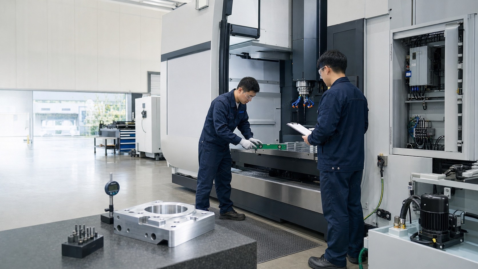
Delivery is not the end of the project
Unloading, lifting, levelling, connecting power, air and coolant, and running the first test cut all affect machine accuracy, stability and where warranty responsibility sits later. Even when a machine has passed its Factory Acceptance Test (FAT) at the builder's plant, poor transport, rigging or site utilities can still show up as geometric deviation, spindle noise, drive alarms or unstable machining dimensions after arrival.This is a general practical guide for CNC lathes, machining centres and mill-turn machines. Actual installation conditions, accuracy tolerances and acceptance methods must follow the manufacturer's technical documentation, the sales contract and the acceptance specification agreed by both parties.
1. Before installation: confirm the site
Foundation and floor loading. Ask the supplier for:- Net machine weight and shipping weight
- Base dimensions and supporting-point positions
- Recommended foundation thickness and anchor-bolt arrangement
- Dynamic load and vibration-isolation requirements
- Clearance needed for maintenance and door swing
2. Unloading, lifting and unpacking inspection
Never estimate lifting points from appearance. Follow the manufacturer's lifting diagram for centre of gravity, designated lifting points, sling or wire-rope specification, spreader-bar requirements, forklift pockets and removable components. Lifting a large machine at the wrong angle can deform sheet metal, load the guideways or twist the bed. Record everything at unpacking. Photograph or film from the moment the container doors open, and record:- Container and seal numbers
- Crate and rust-prevention packaging condition
- Signs of impact, tilting or water ingress
- Sheet metal, window and operator-panel condition
- Accessory boxes, tooling and document counts
- Rust-preventive oil and desiccant condition, and shipping brackets
3. Positioning and levelling
Levelling is not about making the machine look level — it is about minimising bed distortion and restoring the designed geometry. A workable sequence:- Set the machine on the specified supporting points and fit levelling pads or anti-vibration mounts.
- Place precision levels at the manufacturer's specified positions and measure both longitudinal and transverse directions.
- Adjust gradually — do not turn one foot a long way in a single step — then lock and re-measure.
- Let the machine settle, re-check, and run a second inspection after commissioning.
4. Connecting utilities
Electrical. Before energising, confirm three-phase input voltage, supply frequency (50 Hz or 60 Hz), phase sequence, voltage fluctuation within the machine's allowance, transformer rating and connection, main cable size, breaker capacity, an independent protective earth, and that nothing inside the cabinet has worked loose in transit. A transformer changes voltage but not frequency. AC motors — coolant pumps, hydraulic pumps, chip conveyors, cooling fans — must match the local frequency. First power-on should be done by a qualified electrician or the builder's engineer; do not close the main breaker before phase sequence, grounding and transformer output are verified. More detail in . Compressed air. Confirm working pressure, peak air consumption, pipe size, air quality, filtration and drying equipment, and the low-pressure alarm. Wet or oily compressed air damages solenoid valves, cylinders, spindle air-purge systems and tool-magazine mechanisms. Coolant, lubricant and hydraulic oil. "Fill the tank" is not enough. Confirm the specified oil grade and viscosity, whether different oils may be mixed, that the lubrication pump has been purged of air, that every lubrication point actually delivers oil, that hydraulic pressure is within spec, coolant concentration and water quality, and that no fitting leaks. Wrong oil can swell seals, damage pumps, starve the slideways or upset the hydraulic system — and can affect warranty. See .5. Pre-power inspection
- All shipping blocks removed
- Spindle, turret, tailstock and table clamps released
- Connectors, terminals and modules in the cabinet secure
- Main input and transformer output correct; grounding complete
- Lubricant, hydraulic oil and coolant levels correct
- Emergency stops, safety doors and interlocks functional
- No tools, timber or packaging inside the travel area
- All axes can safely reference home
6. No-load commissioning
Run the machine empty before any workpiece goes in.- Axes and motion: correct X/Y/Z direction, reference return, rapid traverse without abnormal noise or vibration, software and hardware travel limits, feed rate matching the command, smooth way covers, and cable carriers free of interference.
- Spindle: raise speed in stages rather than going straight to maximum rpm. Watch noise, vibration, temperature rise, load rate, the cooling system, spindle orientation, forward and reverse rotation, and clamp/unclamp action.
- Magazine or turret: every tool station, indexing in both directions, random tool change, continuous change cycles, tool number matching the actual pocket, clamp-confirmation signals, live tooling and C-axis functions, and any interference during the change.
- Peripherals: chip conveyor, chip cart, coolant pump, through-spindle coolant, mist collector, automatic door, bar feeder, parts catcher, robot, probe and tool setter, and the fire-suppression system.
7. Accuracy is more than one report
Acceptance covers several distinct layers that should not be conflated.- Geometric accuracy — table flatness, axis straightness, squareness between axes, spindle face and radial runout, tailstock-to-spindle alignment, and turret or table positioning. ISO 230-1:2012 covers geometric accuracy under no-load or quasi-static conditions, and explicitly does not apply to operational testing such as vibration or stick-slip.
- Positioning and repeatability — a laser interferometer measures positioning error, reversal error and repeatability, using the methods in ISO 230-2. For CNC lathes, ISO 13041-4:2004 builds on ISO 230-2 and specifies the tolerances for linear axes up to 2 000 mm and for rotary axes.
- Circular or contouring performance — a ballbar checks two-axis circular error on machining centres, per ISO 230-4:2022. For turning centres, contouring performance depends on the configuration and the test method agreed between the parties.
- Test piece — passing the geometric tests does not guarantee that real parts pass. A test piece reflects machine geometry, tool and workholding rigidity, spindle thermal stability, servo parameters, cutting conditions, and the program and offsets together. For machining centres, ISO 10791-7:2020 covers finished test-piece accuracy for machining centres with 3 to 5 simultaneous axes. For CNC lathes, check OD, ID, face, taper, roundness, concentricity and surface roughness against the parts you actually make.
8. What the Site Acceptance Test should confirm
The SAT (Site Acceptance Test) is carried out at the buyer's site and is separate from the FAT at the builder's plant. It should cover at least:- Model, serial number and optional equipment
- Transport damage and missing items
- Levelling and installation status
- Power, compressed air and fluids
- Safety functions
- Axes, spindle and tool-changing systems
- Peripherals, program transfer and network functions
- Accuracy tests and test pieces
- Operator and maintenance training
- Documentation and backups
- The list of open items
9. Documents to collect before acceptance
- Operation, maintenance and parts manuals
- Electrical, hydraulic and pneumatic diagrams; lubrication chart
- Recommended spares list and accuracy inspection report
- Spindle and turret data
- Controller parameter backup and the scope of PLC / ladder backup
- Tool and accessory list
- Warranty terms and warranty start date
- Local agent and technical contacts; training records
- CE, UL or other contractually required compliance documents
10. Do not rush to sign an unconditional acceptance
If items remain open, build a punch list recording the description, photos or video, responsible party, corrective action, completion date, retest method, whether production is affected, and whether the item affects the final payment or the warranty start date. Where an issue does not affect safety or basic operation, the parties can agree a conditional acceptance. Where it involves significant accuracy, safety functions, specification mismatch or missing core options, a verbal promise is not a sound way to close the case.Z&Z STROTEC site acceptance checklist
- Before installation: foundation and loading confirmed / machine footprint and service clearance confirmed / voltage, frequency and transformer confirmed / air, oils and coolant ready / lifting equipment and lift-point data confirmed
- On arrival: container and seals photographed / crate and rust protection checked / no visible damage to machine or accessories / packing list verified / any discrepancy reported immediately
- At commissioning: shipping brackets removed / levelling and grounding complete / axes and reference return normal / spindle warmed up in stages / magazine or turret cycle-tested / interlocks and E-stops functional / all peripherals working
- At acceptance: geometric and positioning accuracy meet the contract / test piece meets the agreed tolerance / documents and controller backups received / operator and maintenance training done / open items recorded in writing / warranty start date and service contact confirmed
Acceptance is not "it powers on" or "it cuts". A complete site acceptance confirms installation conditions, safety functions, mechanical operation, geometric accuracy, test-cut results, document handover and after-sales responsibility together. The more clearly issues are recorded during installation, the easier it is for both sides to establish responsibility if downtime, an accuracy dispute or a warranty question comes up later. For cross-border purchases, the more workable approach is to treat FAT, shipping, installation and SAT as one continuous quality-control procedure rather than four unrelated stages. For routine upkeep afterwards, see the .
Connected CNC, Hidden Risk: An OT Cybersecurity Procurement Checklist for Machine Tool Buyers
Commissioning is the last moment when the supplier's engineer, the machine and the network are all in the same room. Accounts, backups and remote-access rules settled at handover cost nothing; the same items raised a year later usually mean another service visit.
The list of networked components inside the machine; default passwords changed and named accounts created; a backup of parameters, PLC program, licences and settings; and a restore that has actually been tried rather than assumed.
Who may connect, through what channel, approved by whom, for how long, and how the plant cuts the session — written down while the commissioning engineer is still on site, rather than negotiated during the first breakdown.
機台到廠,不等於採購案完成
從貨櫃卸機、定位、調整水平,到接通電源、空壓與冷卻系統並完成首次試切,每個環節都可能影響機台精度、穩定性與日後的保固責任歸屬。即使機台已在製造商工廠通過出廠驗收(FAT,Factory Acceptance Test),若運輸、吊裝或現場公用設施配置不當,到廠後仍可能出現幾何精度偏移、主軸異音、驅動器警報或加工尺寸不穩。本文為一般性實務指南,適用於 CNC 車床、加工中心機與車銑複合機。實際安裝條件、精度允收值與驗收方法,仍應以製造商技術文件、買賣合約及雙方確認的驗收規範為準。
1. 安裝前:先確認廠房條件
地基與樓板承載能力——安裝前應先向供應商取得:- 機台淨重與運輸重量
- 底座尺寸與支撐點位置
- 建議地基厚度與地腳螺栓配置
- 動態載重與防振要求
- 維修及開門所需空間
2. 卸櫃、吊裝與開箱檢查
不可依外觀判斷吊點。應依製造商提供的吊裝圖確認機台重心、指定吊點、吊帶或鋼索規格、橫樑需求、堆高機插入口與可拆卸部件。大型機台若吊裝角度不正確,可能造成鈑金變形、導軌受力或床身扭曲。 開箱時立即記錄。建議從貨櫃開門開始全程拍照或錄影,並記錄:- 貨櫃號碼及封條號碼
- 木箱與防鏽包裝狀態
- 是否有撞擊、傾斜或受潮痕跡
- 機台鈑金、玻璃與操作面板狀態
- 配件箱、刀具及文件數量
- 防鏽油與乾燥劑狀態、運輸固定架是否完整
3. 機台定位與水平調整
水平調整不只是讓機台「看起來是水平的」,而是為了減少床身扭曲並恢復設計幾何精度。建議流程:- 將機台放置於指定支撐點,安裝調整墊鐵或防振墊。
- 依製造商指定位置放置精密水平儀,分別測量縱向與橫向水平。
- 逐步調整,不要一次大幅旋轉單一支撐腳;鎖定後重新測量。
- 靜置一段時間再次確認,完成試運轉後進行第二次複檢。
4. 公用設施連接
電源——通電前必須確認三相輸入電壓、電網頻率為 50Hz 或 60Hz、相序、電壓波動範圍、變壓器容量與接法、主電纜線徑、斷路器容量、獨立保護接地,以及控制箱內部是否因運輸而鬆脫。 變壓器只能改變電壓,不能改變頻率。冷卻泵浦、油壓泵、排屑機與散熱風扇等交流馬達,必須確認是否符合當地頻率。第一次通電應由合格電氣人員或原廠工程師執行;不要在尚未確認相序、接地及變壓器輸出前直接開啟主電源。詳細說明請見。 空壓——應確認工作壓力、瞬間耗氣量、管徑、空氣品質、過濾與乾燥設備,以及壓力下降時的警報功能。若壓縮空氣含水或含油過高,可能損壞電磁閥、氣缸、主軸吹氣系統及刀庫機構。 冷卻液、潤滑油與液壓油——不可只按照「油箱加滿」處理。應確認原廠指定油品黏度與等級、不同油品是否可混用、潤滑泵是否完成排氣、各潤滑點是否實際出油、液壓壓力是否在規格內、冷卻液濃度與水質,以及管路接頭是否漏油或漏水。使用錯誤油品可能導致油封膨脹、泵浦損壞、滑道潤滑不足或液壓系統異常,也可能影響保固。切削液的選擇與維護可參考。5. 第一次通電前檢查
- 所有運輸固定塊均已拆除
- 主軸、刀塔、尾座及工作台固定裝置已解除
- 控制箱內插頭、端子與模組沒有鬆脫
- 主電源輸入與變壓器輸出正確、接地已完成
- 潤滑油、液壓油及冷卻液液位正常
- 緊急停止按鈕、安全門與連鎖裝置功能正常
- 行程範圍內沒有工具、木塊或包裝材料
- 各軸可以安全回原點
6. 空機試運轉
在放入工件之前,應先進行無負載測試。- 各軸與運動:X/Y/Z 軸方向正確、回原點功能正常、快速移動無異音或振動、軟體與硬體行程限制正常、進給速度符合指令、導軌護罩運作順暢、電纜拖鏈沒有干涉。
- 主軸:從低速逐步提高轉速,不要首次啟動就直接運轉至最高轉速。觀察噪音、振動、溫升、負載率、冷卻系統、主軸定位、正反轉與夾刀/鬆刀動作。
- 刀庫或刀塔:每一刀位、正反向分度、隨機換刀、連續換刀循環、刀號與實際刀位是否一致、刀具夾緊確認訊號、動力刀具及 C 軸功能,以及換刀過程是否碰撞或干涉。
- 周邊設備:排屑機、集屑車、冷卻泵、高壓中心出水、油霧回收機、自動門、棒材送料機、工件接收器、機械手、探針與對刀儀、自動滅火系統。
7. 精度檢驗不能只看一張報告
精度驗收包含不同層次,不應混為一談。- 幾何精度——工作台平面度、軸向直線度、軸與軸之間的垂直度、主軸端面與徑向跳動、尾座與主軸中心對準、刀塔或工作台定位精度。ISO 230-1:2012 涵蓋工具機在無負載或準靜態條件下的幾何精度測試,但明確不適用於振動、黏滑等操作性能檢查。
- 定位精度與重複定位精度——可使用雷射干涉儀測量各軸定位誤差、反向誤差及重複性,量測方法依 ISO 230-2。對 CNC 車床,ISO 13041-4:2004 以 ISO 230-2 為基礎,規定 2000 mm 以內線性軸與旋轉軸的定位精度及重複性允收值。
- 圓弧或輪廓性能——加工中心可使用球桿儀(ballbar)檢查兩軸聯動的圓弧誤差,方法見 ISO 230-4:2022。車削中心的輪廓性能則依設備配置與雙方約定的測試方法執行。
- 試切件——幾何精度合格不代表實際加工一定合格。試切件可同時反映機台幾何狀態、刀具與夾持剛性、主軸熱穩定性、伺服參數、加工條件與程式補正設定。加工中心試件可參考 ISO 10791-7:2020,該標準涵蓋三軸至五軸同動加工中心的成品試件精度。CNC 車床則應依零件需求檢查外徑、內徑、端面、錐度、真圓度、同軸度及表面粗糙度。
8. SAT 現場驗收應確認什麼?
SAT(Site Acceptance Test,現場驗收測試)是在買方安裝地完成的驗收,與製造商工廠進行的 FAT 不同。建議至少包含:- 機型、序號與選配項目
- 運輸損傷與缺件確認
- 水平與安裝狀態
- 電源、空壓與油品
- 安全功能
- 各軸、主軸與刀庫運轉
- 周邊設備、程式傳輸與網路功能
- 精度測試與試切件
- 操作及維修教育訓練
- 文件與備份交付
- 未完成項目清單
9. 驗收前必須取得的文件
- 操作手冊、維修手冊、零件手冊
- 電氣圖、液壓與氣壓迴路圖、潤滑圖
- 備品清單與精度檢驗報告
- 主軸與刀塔資料
- 控制器參數備份、PLC/梯形圖備份範圍
- 工具與附件清單
- 保固條款、保固起算日
- 當地代理商及技術聯絡方式、教育訓練紀錄
- CE、UL 或其他合約要求文件
10. 發現問題時,不要急著簽「無條件驗收」
若部分項目尚未完成,可建立 Punch List(待改善清單),逐項記錄問題描述、照片或影片、責任單位、改善方式、完成期限、複驗方式、是否影響生產,以及是否影響尾款或保固起算日。 若問題不影響安全與基本運轉,雙方可約定條件式驗收;但涉及重大精度、安全功能、規格不符或核心選配缺失時,不宜只以口頭承諾結案。Z&Z STROTEC 到廠驗收 Checklist
- 安裝前:地基與承載能力已確認/機台尺寸與維修空間已確認/電壓、頻率及變壓器已確認/空壓、油品及冷卻液已準備/吊裝設備與吊點資料已確認
- 到貨時:貨櫃與封條已拍照/外箱及防鏽包裝已檢查/機台與配件沒有明顯損傷/裝箱清單已核對/異常已即時通知相關單位
- 試車時:運輸固定裝置已拆除/水平與接地已完成/各軸與回原點正常/主軸完成分段暖機/刀庫或刀塔完成循環測試/安全連鎖及緊急停止正常/所有周邊設備正常
- 驗收時:幾何與定位精度符合合約/試切件符合允收標準/文件與控制器備份已取得/操作及維修訓練已完成/待改善項目已有書面紀錄/保固起算日與服務窗口已確認
CNC 機台驗收不能只確認「可以開機」或「可以加工」。完整的到廠驗收應同時確認安裝條件、安全功能、機械運轉、幾何精度、試切結果、文件交付與售後責任。越是在裝機初期把問題記錄清楚,日後發生停機、精度爭議或保固問題時,買賣雙方越容易快速釐清責任。對跨國採購而言,較理想的做法是把 FAT、運輸、安裝與 SAT 視為一套連續的品質管理程序,而不是四個互不相關的階段。後續的日常保養請見。
連網 CNC 的隱形風險:工具機買家必備的 OT 資安採購清單
試機交機是供應商工程師、機台與網路最後一次同時在場的時刻。帳號、備份與遠端存取規則在點交時談定幾乎不花成本;同樣的事情等一年後再提,通常就得再排一次服務。
機台內具網路功能的元件清單;預設密碼已更改並建立具名帳號;參數、PLC 程式、授權與設定的備份;以及一次真的試過、而不是假設可行的還原。
誰可以連線、走哪個通道、由誰核准、有效多久、工廠端如何中斷——趁試機工程師還在現場時寫下來,而不是等第一次故障才開始協調。
기계가 도착했다고 구매가 끝난 것은 아닙니다
컨테이너 하역, 위치 결정, 수평 조정부터 전원·공압·절삭유 연결과 첫 시절삭까지, 모든 단계가 기계 정밀도와 안정성, 그리고 이후의 보증 책임 범위에 영향을 줍니다. 제조사 공장에서 출하 검사(FAT, Factory Acceptance Test)를 통과했더라도 운송·인양·현장 유틸리티 조건이 적절하지 않으면 도착 후 기하 정밀도 편차, 주축 이음, 드라이브 알람, 가공 치수 불안정이 나타날 수 있습니다.본 문서는 CNC 선반, 머시닝센터, 밀턴(복합) 기계를 위한 일반적인 실무 가이드입니다. 실제 설치 조건, 정밀도 허용값, 검사 방법은 제조사 기술 문서와 매매 계약, 양측이 합의한 인수 사양을 우선합니다.
1. 설치 전: 공장 조건 확인
기초와 바닥 하중. 설치 전에 공급자로부터 다음을 확보하십시오.- 기계 순중량 및 운송 중량
- 베이스 치수와 지지점 위치
- 권장 기초 두께 및 앵커 볼트 배치
- 동하중 및 방진 요구사항
- 정비 및 도어 개방에 필요한 공간
2. 하역·인양·개봉 검사
외관으로 인양점을 판단해서는 안 됩니다. 제조사 인양도에 따라 무게중심, 지정 인양점, 슬링·와이어 규격, 스프레더 바 필요 여부, 지게차 삽입구, 분리 가능 부품을 확인하십시오. 대형 기계를 잘못된 각도로 인양하면 판금 변형, 가이드 하중, 베드 비틀림이 발생할 수 있습니다. 개봉 시 즉시 기록. 컨테이너 도어 개방 시점부터 사진·영상으로 기록하고 다음을 남기십시오.- 컨테이너 번호 및 실(seal) 번호
- 목상자와 방청 포장 상태
- 충격·기울어짐·침수 흔적 유무
- 판금, 창, 조작 패널 상태
- 부속품 상자, 공구, 서류 수량
- 방청유·제습제 상태 및 운송 고정 브래킷
3. 위치 결정과 수평 조정
수평 조정은 기계를 "수평처럼 보이게" 하는 작업이 아니라, 베드 변형을 줄이고 설계 기하 정밀도를 회복시키는 작업입니다. 권장 순서:- 지정 지지점에 기계를 놓고 조정 받침 또는 방진 마운트를 설치합니다.
- 제조사가 지정한 위치에 정밀 수준기를 놓고 종방향·횡방향을 각각 측정합니다.
- 한 번에 한 다리를 크게 돌리지 말고 단계적으로 조정한 뒤, 고정하고 다시 측정합니다.
- 일정 시간 안정시킨 후 재확인하고, 시운전 완료 후 2차 점검을 실시합니다.
4. 유틸리티 연결
전원. 통전 전에 3상 입력 전압, 계통 주파수 50Hz 또는 60Hz, 상순, 허용 범위 내 전압 변동, 변압기 용량과 결선, 주 케이블 굵기, 차단기 용량, 독립 보호 접지, 그리고 운송 중 제어반 내부 이완 여부를 확인해야 합니다. 변압기는 전압을 바꿀 뿐 주파수를 바꾸지 못합니다. 절삭유 펌프, 유압 펌프, 칩 컨베이어, 냉각 팬 등 교류 모터는 현지 주파수 적합 여부를 반드시 확인하십시오. 최초 통전은 유자격 전기 기술자 또는 제조사 엔지니어가 수행해야 하며, 상순·접지·변압기 출력을 확인하기 전에 주전원을 투입해서는 안 됩니다. 자세한 내용은 를 참고하십시오. 공압. 사용 압력, 순간 소비 유량, 배관 구경, 공기 품질, 필터·드라이어 설비, 압력 저하 시 알람 기능을 확인하십시오. 압축공기에 수분이나 오일이 과다하면 솔레노이드 밸브, 실린더, 주축 에어퍼지, 매거진 기구가 손상될 수 있습니다. 절삭유·윤활유·작동유. "탱크 가득"으로 끝내면 안 됩니다. 제조사 지정 유종의 점도·등급, 이종 유의 혼용 가능 여부, 윤활 펌프 에어빼기 완료, 각 윤활점의 실제 급유, 유압 압력의 규격 내 여부, 절삭유 농도와 수질, 배관 연결부 누유·누수를 확인하십시오. 잘못된 유종은 실 팽윤, 펌프 손상, 습동면 윤활 부족, 유압 이상을 일으킬 수 있고 보증에도 영향을 줄 수 있습니다. 절삭유는 를 참고하십시오.5. 최초 통전 전 점검
- 모든 운송 고정 블록 제거 완료
- 주축·터릿·심압대·테이블 고정 해제
- 제어반 내 커넥터·단자·모듈 이완 없음
- 주전원 입력과 변압기 출력 정상, 접지 완료
- 윤활유·작동유·절삭유 유면 정상
- 비상정지 버튼, 안전문, 인터록 정상
- 이동 범위 내 공구·목재·포장재 없음
- 각 축 원점 복귀 안전 수행 가능
6. 무부하 시운전
공작물을 물리기 전에 무부하 시험을 먼저 수행합니다.- 축과 운동: X/Y/Z 축 방향, 원점 복귀, 급속 이송 시 이음·진동, 소프트·하드 리미트, 지령 대비 이송 속도, 텔레스코픽 커버 동작, 케이블 베어 간섭 여부.
- 주축: 최초부터 최고 회전수로 올리지 말고 저속부터 단계적으로 상승시키며 소음, 진동, 온도 상승, 부하율, 냉각 계통, 주축 오리엔테이션, 정·역회전, 공구 클램프/언클램프 동작을 관찰합니다.
- 매거진·터릿: 전 공구 위치, 정·역 분할, 랜덤 공구 교환, 연속 교환 사이클, 공구 번호와 실제 포트 일치, 클램프 확인 신호, 동력 공구 및 C축 기능, 교환 중 간섭 여부.
- 주변 장치: 칩 컨베이어, 칩 카트, 절삭유 펌프, 주축 관통 절삭유(CTS), 미스트 컬렉터, 자동문, 바피더, 부품 캐처, 로봇, 프로브·툴세터, 자동 소화 장치.
7. 정밀도 검사는 보고서 한 장으로 끝나지 않습니다
정밀도 인수검사는 서로 다른 층위를 포함하므로 혼동해서는 안 됩니다.- 기하 정밀도 — 테이블 평면도, 축 직진도, 축 간 직각도, 주축 단면·반경 런아웃, 심압대와 주축 중심 정렬, 터릿·테이블 위치결정 정밀도. ISO 230-1:2012은 무부하 또는 준정적 조건의 기하 정밀도 시험을 다루며, 진동·스틱슬립 같은 운전 성능 시험에는 적용되지 않는다고 명시합니다.
- 위치결정 정밀도·반복 정밀도 — 레이저 간섭계로 각 축의 위치결정 오차, 역전 오차, 반복성을 측정하며 측정 방법은 ISO 230-2를 따릅니다. CNC 선반의 경우 ISO 13041-4:2004가 ISO 230-2를 기반으로 2 000 mm 이하 직선축과 회전축의 허용값을 규정합니다.
- 원호·윤곽 성능 — 머시닝센터는 볼바(ballbar)로 2축 동시 원호 오차를 확인하며 방법은 ISO 230-4:2022를 따릅니다. 터닝센터의 윤곽 성능은 설비 구성과 양측이 합의한 시험 방법에 따릅니다.
- 시절삭품 — 기하 정밀도 합격이 실제 가공 합격을 보장하지는 않습니다. 시절삭품은 기계 기하 상태, 공구·클램핑 강성, 주축 열 안정성, 서보 파라미터, 가공 조건, 프로그램과 보정값을 함께 반영합니다. 머시닝센터는 ISO 10791-7:2020을 참고할 수 있으며, 3~5축 동시 가공 머시닝센터의 완성 시험편 정밀도를 다룹니다. CNC 선반은 실제 부품 요구에 따라 외경, 내경, 단면, 테이퍼, 진원도, 동심도, 표면 거칠기를 확인합니다.
8. SAT(현장 인수검사)에서 확인할 것
SAT(Site Acceptance Test)는 구매자 설치 현장에서 수행하는 인수검사로, 제조사 공장에서 하는 FAT와 다릅니다. 최소한 다음을 포함하는 것이 좋습니다.- 기종, 시리얼 번호, 옵션 사양
- 운송 손상 및 결품 확인
- 수평 및 설치 상태
- 전원, 공압, 유종
- 안전 기능
- 각 축·주축·공구 교환 계통 운전
- 주변 장치, 프로그램 전송, 네트워크 기능
- 정밀도 시험 및 시절삭품
- 조작·정비 교육
- 문서 및 백업 인도
- 미완료 항목 리스트
9. 인수 전 반드시 확보할 문서
- 조작 매뉴얼, 정비 매뉴얼, 부품 매뉴얼
- 전기 도면, 유압·공압 회로도, 윤활 계통도
- 예비품 리스트, 정밀도 검사 성적서
- 주축·터릿 자료
- 제어기 파라미터 백업, PLC·래더 백업 범위
- 공구·부속품 리스트
- 보증 조건과 보증 개시일
- 현지 대리점 및 기술 연락처, 교육 기록
- CE, UL 등 계약상 요구 문서
10. 문제가 있을 때 "무조건 인수"에 서둘러 서명하지 마십시오
미완료 항목이 있다면 펀치 리스트(개선 목록)를 만들어 문제 내용, 사진·영상, 책임 주체, 개선 방법, 완료 기한, 재검사 방법, 생산 영향 여부, 잔금·보증 개시일 영향 여부를 항목별로 기록하십시오. 안전과 기본 운전에 영향이 없는 사안이라면 양측이 조건부 인수를 합의할 수 있습니다. 다만 중대한 정밀도, 안전 기능, 사양 불일치, 핵심 옵션 누락이 걸린 경우에는 구두 약속만으로 마무리하지 않는 것이 좋습니다.Z&Z STROTEC 현장 인수검사 체크리스트
- 설치 전: 기초·하중 확인 / 기계 치수와 정비 공간 확인 / 전압·주파수·변압기 확인 / 공압·유종·절삭유 준비 / 인양 장비와 인양점 자료 확인
- 입고 시: 컨테이너·실 사진 촬영 / 외장·방청 포장 점검 / 기계·부속품 외관 손상 없음 / 패킹리스트 대조 / 이상 발생 시 즉시 통보
- 시운전 시: 운송 고정 장치 제거 / 수평·접지 완료 / 각 축·원점 복귀 정상 / 주축 단계별 예열 완료 / 매거진·터릿 사이클 시험 완료 / 인터록·비상정지 정상 / 주변 장치 전체 정상
- 인수 시: 기하·위치결정 정밀도 계약 부합 / 시절삭품 합격 기준 충족 / 문서·제어기 백업 수령 / 조작·정비 교육 완료 / 미개선 항목 서면 기록 / 보증 개시일과 서비스 창구 확인
CNC 기계 인수검사는 "전원이 들어온다", "가공이 된다"만 확인하는 절차가 아닙니다. 완전한 현장 인수는 설치 조건, 안전 기능, 기계 운전, 기하 정밀도, 시절삭 결과, 문서 인도, 사후 책임을 함께 확인합니다. 설치 초기에 문제를 명확히 기록해 둘수록 이후 정지, 정밀도 분쟁, 보증 문제가 생겼을 때 양측이 책임을 빠르게 정리할 수 있습니다. 국제 구매에서는 FAT·운송·설치·SAT를 서로 무관한 네 단계가 아니라 하나의 연속된 품질관리 절차로 보는 편이 현실적입니다. 이후 일상 보전은 를 참고하십시오.
네트워크에 연결된 CNC의 보이지 않는 위험: 공작기계 구매자를 위한 OT 사이버 보안 체크리스트
시운전과 인수는 공급사 엔지니어와 장비, 네트워크가 마지막으로 한자리에 모이는 시점입니다. 계정·백업·원격 접속 규칙을 인수 시점에 정해 두면 비용이 들지 않지만, 같은 항목을 1년 뒤에 꺼내면 대개 서비스 방문이 다시 필요합니다.
장비 내 네트워크 구성요소 목록, 기본 비밀번호 변경과 개인 계정 생성, 파라미터·PLC 프로그램·라이선스·설정의 백업, 그리고 가정이 아니라 실제로 시도해 본 복원입니다.
누가, 어떤 경로로, 누구의 승인을 받아, 얼마 동안 접속하며, 공장은 어떻게 차단하는지를 시운전 엔지니어가 현장에 있을 때 문서로 남기십시오. 첫 고장이 났을 때 협의할 일이 아닙니다.
장비 모델명, 부품 번호 또는 현장 사진을 보내주시면 공급 가능 여부와 가격을 회신드립니다.
Multi-brand selection rather than one factory, spec and compatibility checks in writing, a test cut and inspection at the plant before the machine ships, export documentation, and the same part number still available years later. Installation and after-sales in Korea, Brazil, Switzerland and Argentina run through local agents; for other markets we supply parts and components.
不綁單一工廠的多品牌選型、白紙黑字的規格與相容性確認、出貨前在工廠端試車驗機、出口文件,以及數年後仍拿得到的同一料號。韓國、巴西、瑞士、阿根廷的安裝與售後由在地服務商執行,其他市場我們供應零件與零組件。
단일 공장에 묶이지 않는 다중 브랜드 선정, 문서로 남기는 사양·호환성 확인, 선적 전 공장 시운전과 검사, 수출 서류, 그리고 수년 뒤에도 확보 가능한 동일 품번. 한국·브라질·스위스·아르헨티나의 설치와 애프터서비스는 현지 대리점이 담당하며, 그 외 시장에는 부품을 공급합니다.