 Z&Z STROTEC
How to Identify a Replacement Chuck or Collet Chuck
夾頭與筒夾更換辨識指南 · 교체용 척·콜릿 척 식별 가이드
View interactive version · 完整互動版 · 인터랙티브 버전 →When a chuck is damaged, loses gripping force or accuracy, or the original model is discontinued, a replacement cannot be chosen from appearance or machine brand alone. Two chucks that look alike may differ in spindle nose, through-hole, cylinder interface, jaw serration pitch or permitted speed — differences that prevent mounting, or allow mounting but not reliable clamping or accuracy.
Before requesting a quotation, please prepare the 10 items below. The more complete the information, the shorter the confirmation time and the lower the risk of selecting the wrong specification.
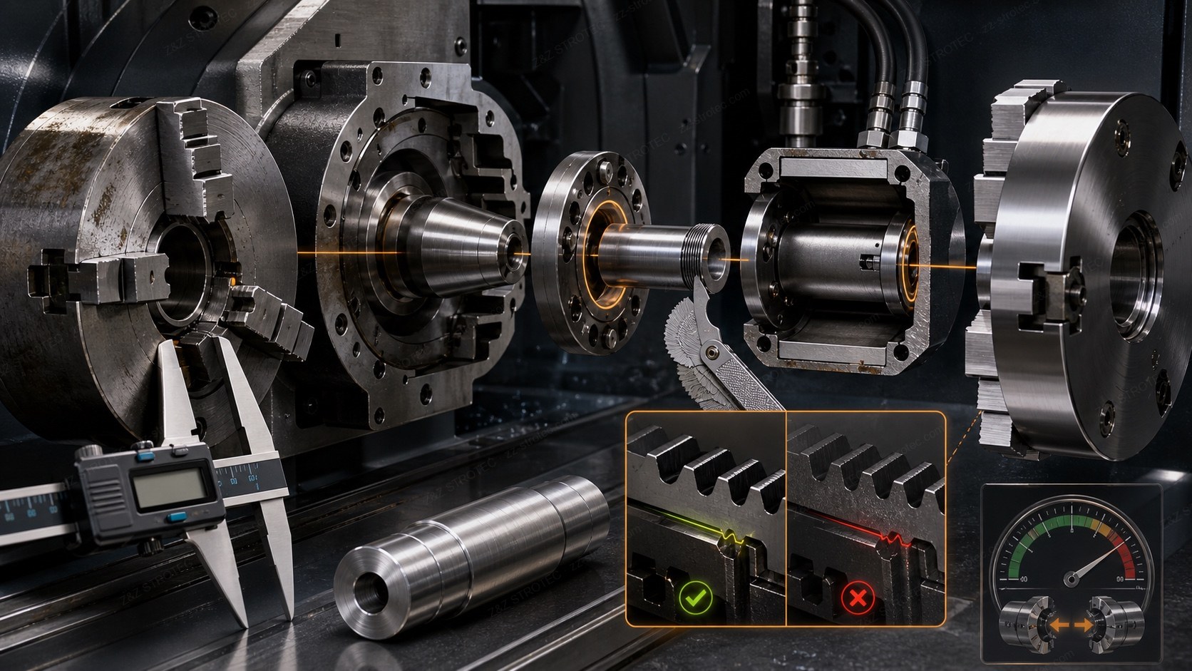
The 10-point checklist for identifying a replacement chuck
1. Lathe brand, full model and year
Give the full model, not just the brand — spindle specification and workholding configuration differ between models from the same builder. State the machine type as well: fixed-headstock lathe, Swiss-type, twin-spindle or vertical. Swiss-type machines clamp mainly with collets at the spindle, which is a different system from the hydraulic chuck on a conventional lathe. Include the serial number or year if the nameplate shows one.
2. Spindle nose designation
This is the first condition that decides whether a chuck will mount at all. Common standards are the A2 series (A2-4, A2-5, A2-6, A2-8, A2-11), located on a short taper and bolted, and the D1 camlock series (D1-4, D1-6, D1-8); some machines use a proprietary nose. Confirm which series and which number, and photograph the spindle face. The taper number and bolt pattern are what identify it — "an 8-inch spindle" is not enough.
3. Brand, model and serial of the existing chuck
Photograph the complete nameplate rather than sending a partial or blurred image. It normally carries the brand, model, size, maximum permitted speed and maximum hydraulic pressure. The original model number matters, but some numbers have been revised, discontinued, or coded differently between markets, so it cannot be the sole basis for identification.
4. Chuck type and size
State what is fitted now and what is intended: through-hole (hollow) for bar work, solid for individual blanks, a collet chuck where concentricity and a short clamping length matter, or a face plate or special fixture for irregular parts. Note also whether the action is draw-back or push-out, since it changes how the part is located axially. Size is given in inches — 5", 6", 8", 10", 12" are common — and is independent of the spindle nose number.
5. Through-hole diameter
For continuous bar work, confirm three diameters: the spindle bore, the draw tube inner diameter and the chuck through-hole. The smallest of the three is the real bar capacity, and in practice the draw tube is frequently the limit rather than the spindle bore. Individual-blank work is not bound by this, but it still applies if the part is long enough to enter the spindle.
6. Rotating cylinder and draw tube interface
The chuck does not generate the clamping force; it comes from the rotating hydraulic cylinder at the rear of the spindle, and that cylinder is tied tightly to the spindle itself. It has to match the draw tube thread, the spindle bore and the bearing bore exactly — different lathes differ in both nose designation and bore, for example A2-6 against A2-8, or a bore of ∅81 mm against ∅91 mm. Confirm the cylinder brand and model, hollow or solid, stroke, maximum draw force and working pressure, and the thread and length of the draw tube or draw bar. Thrust, stroke and permitted maximum speed must be checked against the machine's own hydraulic circuit and system pressure setting. A wrong model may simply not fit; worse, it can leave gripping force short — and insufficient grip can throw the workpiece during machining. The rotating cylinder sits close to the machine side, so its specification usually has to be confirmed with the builder and its lead time is longer than the chuck itself. Raise it early and send a photograph of the current arrangement.
7. Jaw specification
Confirm the number of jaws (2, 3 or 4), soft or hard, and the serration pitch — commonly 1.5 mm × 60°, 3 mm × 60° or 1/16" × 90°. Pitch is the item most often overlooked and most often wrong: jaws of a different pitch will not interchange even when the chuck size matches. But pitch alone is not the whole interface: the slot width, the locating hole spacing and the bolt specification on the mating face are also part of it, and each chuck brand has its own patented or proprietary arrangement. Photograph the serrations close up, ideally against a rule, and give measured dimensions if the nameplate is worn. Where a gantry loader or robot is fitted, jaw outside diameter, height and clamping range have to match the machine's travel limits and the loader's path, or geometric interference and a crash become likely at speed. Say as well whether one-piece hard jaws, exchangeable carriers, or special forms for thin-walled, irregular or internally gripped parts are needed. Soft jaws are consumable and bored to suit the part; jaws and carriers are mostly specific to the chuck brand, so the model has to be confirmed with the manufacturer before ordering.
8. Collet type and clamping range
For a collet chuck, confirm the type and range. Spindle collets are commonly 5C, 16C, 22C or R8, plus machine-specific designs. Each collet covers a limited effective range — going outside it reduces gripping force and concentricity — so give the workpiece diameter and tolerance range.
8b. Swiss-type collets and guide bushings
Workholding on a Swiss-type lathe (Citizen Cincom, STAR, TSUGAMI, Miyano and Taiwanese sliding-headstock models) is fundamentally different from a conventional lathe. The collets used at the main and sub spindle, and the guide bushing that supports the bar at the cutting point, are made to the machine model: taper angle, outside diameter, length and the rear draw thread pitch are all proprietary. The machining mode changes the specification too — whether the machine is built with a removable guide bushing or runs guide-bushing-less directly alters the bushing specification and its mounting length. Without the complete model and serial number it is easy to receive a collet of the wrong length or taper, which shows up as poor bar feeding, chatter, or severe runout on the finished part. Note that ER collets (ER16, ER20, ER25, ER32 and so on) belong to the tool side, holding cutting tools in live and static holders — a different system from the spindle collets that grip the workpiece, so state which side you mean.
9. Workpiece data
The workholding solution is ultimately decided by the part, so provide the outside diameter range and the length of the clamped section, the material and weight, whether the part is thin-walled, deformable or already finished, whether the clamped section is raw, cast or machined, whether a second clamping for finishing is involved, and the concentricity or runout requirement. Thin-walled parts and finished surfaces usually need lower gripping force or a special jaw form — the opposite of the intuition that more force is better.
10. Speed and gripping force
Give the maximum spindle speed actually used. A chuck's rated maximum speed is a safety limit, not a recommendation, and centrifugal force acting on the jaws reduces the actual gripping force as speed rises, so the force available at working speed can be well below the static figure. On large diameters and heavy parts this affects both safety and machining stability directly. For high-speed work, confirm the chuck's balance requirement and whether dynamic balancing is needed.
The three essentials to send with an inquiry
- Machine nameplate photo — complete model, year of manufacture and serial number. The same model can be revised between production years.
- Nameplate or stamping on the existing part — the brand, model, part number or rotation arrow on the jaw carrier, cylinder or collet.
- Measured key dimensions — where the nameplate is worn, send caliper measurements: hole spacing, outside diameter, length and thread pitch.
Useful additions: the spindle face showing the nose type and bolt pattern, a close-up of the jaw serrations with a rule alongside, the rear of the spindle with the rotating cylinder, and the workpiece or its drawing.
Dimensions: spindle nose designation, chuck size in inches, through-hole diameter, draw tube inner diameter, workpiece diameter range and clamped length, and maximum working speed.
Common inquiry mistakes
- Deriving the spindle nose from the chuck size. An 8" chuck does not imply a particular nose number; the two must be confirmed separately.
- Replacing the chuck without checking the cylinder. Mismatched stroke or draw force leaves the part under-clamped or the stroke exhausted.
- Ignoring jaw serration pitch. Same chuck size, different pitch — the jaws will not interchange.
- Deriving bar capacity from the maximum turning diameter. Use the smallest of spindle bore, draw tube inner diameter and chuck through-hole.
- Confusing ER collets with spindle collets. The first holds tools, the second holds the workpiece.
- Assuming more gripping force is always better. Thin-walled and finished parts need appropriate force and the right jaw form.
- Overlooking how speed affects gripping force. The rated maximum is a safety limit, and available force falls as speed rises.
All replacement and compatibility decisions should ultimately rest on the machine manufacturer's original specification, the official drawings, and acceptance conditions agreed between both parties. This article provides general technical guidance and does not replace them.
Need help identifying a replacement chuck or collet?
Z&Z STROTEC supplies hydraulic chucks, collet chucks and collets for CNC lathes, and helps confirm interface and specification compatibility when replacing them.
Some items — jaws and jaw carriers, rotating cylinders, and the machine-specific collets used on Swiss-type lathes — are mostly proprietary to a chuck brand or a machine, so the model and dimensions have to be confirmed with the original manufacturer first and lead times are usually longer. We raise these during the confirmation stage and help verify them with the builder, so nothing surfaces as a missing part after the change.
Send the photographs and dimensions above and we will help confirm which models are workable and what else has to be handled alongside.
Chuck Gripping Force at Speed: Why the Hydraulic Gauge Is Not the Force on Your Workpiece
Before replacing a chuck, confirm that grip is really what is missing. The column follows the published route from cutting force to the setting you need, shows how much speed takes back, and lists the adjustments that move more than the pressure valve.
In the maker's own worked example the centrifugal force of the jaws at 2,000 rpm is 3,111 N, roughly a quarter of the 12,077 N that cut required. A grip measured at zero rpm is not the grip you have during the cut.
Hard jaws carry the least mass and lose the least force, and the length factor should not be less than 2 for unsupported turning but can come down to 1 with a tailstock or steady rest, which halves the force required.
夾頭損壞、夾持力下降、精度跑掉,或原廠型號停產時,不能只憑外觀或機台品牌選購替代品。兩顆看起來相似的夾頭,只要主軸鼻端、通過孔、油壓缸介面、爪座齒距或允許轉速不同,就可能裝不上去,或裝得上去卻夾不穩、精度不到。
向供應商詢價前,請準備以下 10 項資料。資料越完整,越能縮短確認時間並降低選錯規格的風險。
夾頭與筒夾更換/詢價的 10 項辨識清單
1. 車床品牌、完整型號與出廠年份
請提供完整型號,不只是品牌;同一品牌不同型號的主軸規格與夾持配置可能完全不同。同時說明機台型態:一般固定主軸車床、走心式、雙主軸或立式。走心式的主軸夾持以筒夾為主,與一般車床的油壓夾頭是不同系統。銘牌上若有序號或製造年份,請一併提供。
2. 主軸鼻端規格
這是決定夾頭能不能裝上去的第一個條件。常見規格為 A2 系列(A2-4、A2-5、A2-6、A2-8、A2-11),以短錐面定位、螺栓固定;以及 D1 凸輪鎖定系列(D1-4、D1-6、D1-8)。部分機台使用專用鼻端。請確認是 A2 或 D1、幾號,並拍攝主軸端面照片。錐度號數與螺栓孔分布才是判定依據,只說「8 吋主軸」無法確認。
3. 現有夾頭的品牌、型號與序號
請拍攝完整銘牌,不要只傳局部或模糊照片。銘牌上通常有品牌、型號、尺寸、允許最高轉速與最大油壓。原廠型號很重要,但部分型號可能已改版、停產,或在不同市場使用不同編碼,因此不能單獨作為判定依據。
4. 夾頭型式與尺寸
請說明目前使用與預計更換的型式:中空(貫穿)用於棒料生產、中實用於單件毛胚、筒夾夾頭用於重視同心度與短夾持長度的場合、面盤或特殊治具用於異形件。同時說明是後拉式或前推式,這會影響工件的軸向定位方式。尺寸以吋表示,常見 5"、6"、8"、10"、12",且與主軸鼻端號數無關。
5. 通過孔直徑
若要以棒料連續生產,請確認三個孔徑:主軸通孔、拉管內徑、夾頭通過孔。三者取最小值才是實際可用的棒徑上限,實務上限制往往是拉管內徑而不是主軸通孔。單件毛胚生產不受此限,但工件若較長需伸入主軸,仍需確認。
6. 旋轉油壓缸型號與拉管介面
夾頭本身不會產生夾持力,力量來自主軸後端的旋轉油壓缸,而油壓缸與主軸是緊密綁定的。它必須與主軸後端的拉管螺紋、主軸通孔徑及培林內徑完全一致——不同車床的鼻端規格與貫通穴徑差異很大,例如 A2-6 與 A2-8,穴徑 ∅81 mm 與 ∅91 mm。請確認油壓缸品牌與型號、中空或中實、行程、最大拉力與使用油壓、拉桿或拉管的螺紋規格與長度。推力、行程與容許最高轉速,必須嚴格對照機台原廠的液壓迴路與系統壓力設定。型號對應錯誤,輕則無法安裝,重則夾持力不足——而夾持力不足可能在加工中拋出工件。旋轉油壓缸屬於較接近機台端的零件,規格通常需向原廠確認,交期也比夾頭本體長,建議提早提出並提供現有配置照片。
7. 爪的規格
請確認爪數(2 爪、3 爪或 4 爪)、軟爪或硬爪,以及爪座齒距——常見 1.5 mm × 60°、3 mm × 60° 或 1/16" × 90°。齒距是最容易被忽略卻最容易出錯的一項:齒距不同的爪即使夾頭尺寸相同也無法互換。但介面不只齒距:接合面的滑槽寬度、定位鎖孔距與螺栓規格同樣是判定條件,各品牌夾頭皆有其專利或專屬設計。請拍攝爪座齒部近照,最好附上尺規;銘牌若已磨損,請提供游標卡尺的實測尺寸。若搭配門型機械手或自動化上下料,爪的外徑、高度與夾持範圍必須與機台極限行程及手臂路徑完全匹配,否則在高速旋轉或快速移動時容易發生幾何干涉或撞機。並說明是否需要一體式硬爪、可換式爪座,或薄壁件、異形件、內撐夾持用的特殊爪型。軟爪屬消耗品,可依工件搪修;爪與爪座多為各夾頭品牌的專屬規格,訂購前需向原廠確認型號。
8. 筒夾型式與夾持範圍
若使用筒夾夾頭,請確認型式與夾持範圍。主軸筒夾常見 5C、16C、22C、R8 及各機台專用型式。每支筒夾的有效夾持範圍有限,超出範圍會導致夾持力下降與同心度變差,請提供工件外徑與公差範圍。
8b. 走心式機台專用筒夾與導套
走心式車床(Citizen Cincom、STAR、TSUGAMI、Miyano 及台灣的走心機種)的工件夾持系統,與一般車床有本質上的不同。主軸與副主軸所使用的筒夾,以及在切削點支撐棒材的導套,都是針對機台型號量身打造:錐度角度、外徑、長度及後端拉力的螺紋距,皆為專屬規格。加工模式也會改變規格——機台是否配備可拆式導套或採無導套設計,會直接改變所需的導套規格與安裝長度。若沒有提供完整機台型號與序號,極容易買到長度或錐度不合的筒夾,結果表現為棒材送料不順、震刀,或加工件嚴重偏擺。注意:ER 筒夾(ER16、ER20、ER25、ER32 等)屬於刀具夾持端,用於動力刀座與靜態刀座,與主軸工件夾持的筒夾是不同系統,詢價時請說明是哪一端。
9. 工件資料
夾持方案最終由工件決定,請提供:工件外徑範圍與夾持段長度、材質與重量、是否為薄壁或易變形、夾持段是毛胚面/鑄面/已加工面、是否需要二次夾持精修,以及對同心度或跳動的要求。薄壁件與已精加工面通常需要較低夾持力或特殊爪型,這與「夾持力越大越好」的直覺相反。
10. 轉速與夾持力
請提供實際使用的最高主軸轉速。夾頭的允許最高轉速是安全上限而非建議值,且隨著轉速提高,作用在爪上的離心力會使實際夾持力下降,工作轉速下可用的夾持力可能明顯低於靜態值。加工大直徑或重工件時,這會直接影響安全與加工穩定性。高轉速應用請一併確認夾頭的平衡等級與是否需要動平衡。
詢價時建議備妥的「合規三寶」
- 機台銘牌照片——完整型號、製造年份及機台序號。同型號不同年份可能改版。
- 原有配件的銘牌或鋼印照片——原爪座、油壓缸或筒夾上的品牌、型號、料號或旋向箭頭。
- 關鍵尺寸實測——銘牌若已磨損,請提供游標卡尺的實測尺寸:孔距、外徑、長度與螺紋距。
另建議附上:可看出鼻端型式與螺栓孔分布的主軸端面、附尺規的爪座齒部近照、主軸後端與旋轉油壓缸、工件實物或圖面。
尺寸:主軸鼻端號數、夾頭尺寸(吋)、通過孔直徑、拉管內徑、工件外徑範圍與夾持長度、最高使用轉速。
常見的詢價錯誤
- 用夾頭尺寸推算主軸鼻端。 8 吋夾頭不等於特定鼻端號數,兩者必須分別確認。
- 只換夾頭,沒確認油壓缸。 行程與拉力不匹配時,會出現夾不緊或行程用盡。
- 忽略爪座齒距。 夾頭尺寸相同但齒距不同,爪無法互換。
- 用最大車削直徑推算棒徑。 應取主軸通孔、拉管內徑與夾頭通過孔的最小值。
- 把 ER 筒夾與主軸筒夾混為一談。 前者是刀具端,後者是工件端。
- 假設夾持力越大越好。 薄壁件與精加工面需要的是適當夾持力與合適爪型。
- 忽略轉速對夾持力的影響。 允許最高轉速是安全上限,實際夾持力會隨轉速下降。
所有替換與相容性判定,最終仍應以機台製造商的原始規格書、正式圖面及雙方確認的允收條件為準。本文提供一般性技術指引,不取代上述文件。
需要協助辨識替換用夾頭或筒夾?
Z&Z STROTEC 供應 CNC 車床用油壓夾頭、筒夾夾頭與筒夾,並協助確認更換時的介面與規格相容性。
部分項目——例如爪與爪座、旋轉油壓缸,以及走心式車床的機台專用筒夾——多屬各品牌或機台的專屬規格,需要先向原廠確認型號與尺寸才能對應,交期通常也較長。這類項目我們會在確認階段一併提出並協助查證,以免更換後才發現缺件。
請提供上述照片與尺寸,我們會協助確認可用型號與需要一併處理的項目。
夾持力不等於油壓表讀值:轉速、爪高與夾持位置如何吃掉你的夾持力
換夾頭之前,先確認夾持力是不是真的不足。這篇專欄整理了需求夾持力的計算路徑、轉速拿走多少,以及哪些調整比動壓力閥更有效。
在原廠的計算範例中,2,000 rpm 時爪的離心力為 3,111 N,約為該次切削所需 12,077 N 的四分之一。靜止時量到的夾持力,不等於切削當下的夾持力。
硬爪質量小、損失最少;一般無支撐車削的長度係數不應小於 2,改用尾座或中心架支撐後可降到 1,需求夾持力等於直接減半。
척이 손상되었거나 파지력·정밀도가 떨어졌거나 원 모델이 단종되었을 때, 외관이나 기계 브랜드만으로 대체품을 고를 수 없습니다. 비슷해 보이는 두 척도 주축 노즈, 관통 구멍, 실린더 인터페이스, 조 세레이션 피치, 허용 회전수가 다르면 장착이 되지 않거나, 장착되더라도 안정적인 파지와 정밀도를 얻지 못합니다.
견적을 요청하기 전에 아래 10가지 항목을 준비해 주십시오. 자료가 완전할수록 확인 시간이 짧아지고 규격 오선정 위험이 줄어듭니다.
교체용 척 식별을 위한 10가지 체크리스트
1. 선반 브랜드, 전체 모델명, 제조 연도
브랜드만이 아니라 전체 모델명을 제공해 주십시오. 같은 제조사라도 모델에 따라 주축 사양과 척킹 구성이 다릅니다. 고정 주축 선반, 스위스형, 트윈 스핀들, 수직형 등 기계 형태도 알려 주십시오. 스위스형은 주축에서 콜릿으로 파지하므로 일반 선반의 유압 척과는 다른 시스템입니다.
2. 주축 노즈 규격
척의 장착 가능 여부를 결정하는 첫 번째 조건입니다. 숏 테이퍼 위치 결정에 볼트로 고정하는 A2 시리즈(A2-4·A2-5·A2-6·A2-8·A2-11)와 캠락 방식의 D1 시리즈(D1-4·D1-6·D1-8)가 일반적이며, 전용 노즈를 쓰는 기계도 있습니다. 어느 시리즈의 몇 번인지 확인하고 주축 단면 사진을 보내 주십시오.
3. 기존 척의 브랜드·모델·일련번호
부분 사진이나 흐릿한 사진이 아니라 명판 전체를 촬영해 주십시오. 브랜드, 모델, 크기, 허용 최고 회전수, 최대 유압이 표기되어 있습니다. 원 모델 번호는 중요하지만 개정·단종되었거나 시장별로 코드가 다를 수 있어 단독 판단 근거로는 부족합니다.
4. 척의 종류와 크기
현재 사용 중인 것과 교체 예정인 것을 알려 주십시오. 봉재 가공용 관통형(중공), 단품 소재용 솔리드형, 동심도와 짧은 파지 길이가 중요한 경우의 콜릿 척, 이형 부품용 페이스 플레이트·전용 지그가 있습니다. 인장식인지 압출식인지도 알려 주십시오. 크기는 인치로 표기하며(5"·6"·8"·10"·12") 주축 노즈 번호와는 무관합니다.
5. 관통 구멍 지름
봉재 연속 가공이라면 주축 관통 구멍, 드로우 튜브 내경, 척 관통 구멍 세 가지를 확인해 주십시오. 셋 중 최솟값이 실제 봉재 상한이며, 실무에서는 주축 관통 구멍보다 드로우 튜브가 제한인 경우가 많습니다.
6. 로터리 실린더와 드로우 튜브 인터페이스
척 자체는 파지력을 만들지 않으며, 힘은 주축 후단의 로터리 유압 실린더에서 나옵니다. 이 실린더는 주축과 밀접하게 묶여 있어 드로우 튜브 나사, 주축 관통 구멍 지름, 베어링 내경이 정확히 일치해야 합니다. 예를 들어 A2-6과 A2-8, 관통 지름 ∅81 mm과 ∅91 mm은 전혀 다릅니다. 실린더 브랜드·모델, 중공·솔리드, 스트로크, 최대 인장력과 사용 유압, 드로우 튜브의 나사 규격과 길이를 확인해 주십시오. 추력·스트로크·허용 최고 회전수는 기계 원 제조사의 유압 회로와 시스템 압력 설정에 맞춰 엄격히 대조해야 합니다. 모델이 맞지 않으면 장착이 불가하거나, 심할 경우 파지력 부족으로 가공 중 공작물이 튀어나갈 수 있습니다.
7. 조(Jaw) 사양
조 수(2·3·4), 소프트·하드 여부, 세레이션 피치(일반적으로 1.5 mm × 60°, 3 mm × 60°, 1/16" × 90°)를 확인해 주십시오. 피치는 가장 자주 간과되면서 가장 자주 틀리는 항목으로, 피치가 다르면 척 크기가 같아도 호환되지 않습니다. 다만 인터페이스는 피치만이 아닙니다. 접합면의 슬롯 폭, 위치 결정 홀 간격, 볼트 규격도 판정 조건이며 척 브랜드마다 고유 설계를 가집니다. 세레이션을 근접 촬영하고 명판이 마모되었다면 실측 치수를 제공해 주십시오. 갠트리 로더나 로봇을 함께 쓰는 경우, 조의 외경·높이·파지 범위가 기계의 이동 한계와 로더 경로에 정확히 맞아야 고속 회전이나 급속 이송 시 간섭·충돌을 피할 수 있습니다.
8. 콜릿 종류와 파지 범위
콜릿 척이라면 종류와 범위를 확인해 주십시오. 주축 콜릿은 5C·16C·22C·R8 및 기계 전용 설계가 일반적입니다. 각 콜릿의 유효 범위는 제한적이므로 공작물 외경과 공차 범위를 알려 주십시오.
8b. 스위스형 전용 콜릿과 가이드 부시
스위스형 선반(Citizen Cincom, STAR, TSUGAMI, Miyano 및 대만 슬라이딩 헤드스톡 기종)의 공작물 파지 시스템은 일반 선반과 본질적으로 다릅니다. 주축·부주축용 콜릿과 절삭점에서 봉재를 지지하는 가이드 부시는 기계 모델에 맞춰 제작되며, 테이퍼 각도, 외경, 길이, 후단 인장 나사 피치가 모두 전용 규격입니다. 가공 방식도 규격을 바꿉니다. 착탈식 가이드 부시 사양인지 무(無)가이드 부시 방식인지에 따라 필요한 부시 규격과 장착 길이가 달라집니다. 완전한 모델명과 일련번호가 없으면 길이나 테이퍼가 맞지 않는 콜릿을 받기 쉬우며, 이는 봉재 이송 불량·채터·심한 런아웃으로 나타납니다. ER 콜릿은 공구 측이며 주축의 공작물 파지용 콜릿과는 다른 시스템입니다.
9. 공작물 정보
척킹 방안은 결국 부품이 결정합니다. 외경 범위와 파지 구간 길이, 재질과 중량, 박육·변형 가능성, 파지면이 소재면·주물면·가공면인지, 2차 파지 정삭 여부, 동심도·런아웃 요구사항을 알려 주십시오. 박육 부품과 가공 완료면은 대개 낮은 파지력이나 전용 조가 필요하며, 이는 '파지력은 클수록 좋다'는 통념과 반대입니다.
10. 회전수와 파지력
실제 사용하는 최고 주축 회전수를 알려 주십시오. 척의 허용 최고 회전수는 권장값이 아니라 안전 한계이며, 회전수가 올라가면 조에 작용하는 원심력이 실제 파지력을 낮춥니다. 대직경·중량 부품에서는 안전과 가공 안정성에 직접 영향을 줍니다. 고속 용도에서는 척의 밸런스 등급과 동적 밸런싱 필요 여부도 확인하십시오.
문의 시 준비를 권장하는 세 가지 필수 자료
- 기계 명판 사진 — 전체 모델명, 제조 연도, 일련번호. 같은 모델도 연도에 따라 개정될 수 있습니다.
- 기존 부품의 명판 또는 각인 사진 — 조 캐리어·실린더·콜릿의 브랜드, 모델, 부품번호, 회전 방향 화살표.
- 핵심 치수 실측 — 명판이 마모된 경우 캘리퍼 실측값(홀 간격, 외경, 길이, 나사 피치)을 보내 주십시오.
추가로 유용한 자료: 노즈 형식과 볼트 배치가 보이는 주축 단면, 자를 함께 놓은 세레이션 근접 사진, 주축 후단과 로터리 실린더, 공작물 실물 또는 도면.
치수: 주축 노즈 번호, 척 크기(인치), 관통 구멍 지름, 드로우 튜브 내경, 공작물 외경 범위와 파지 길이, 최고 사용 회전수.
문의 시 자주 발생하는 오류
- 척 크기로 주축 노즈를 추정합니다. 8" 척이 특정 노즈 번호를 의미하지 않으며 각각 확인해야 합니다.
- 척만 교체하고 실린더를 확인하지 않습니다. 스트로크·인장력이 맞지 않으면 파지 부족이나 스트로크 소진이 발생합니다.
- 조 세레이션 피치를 간과합니다. 척 크기가 같아도 피치가 다르면 호환되지 않습니다.
- 최대 선삭 지름으로 봉재 지름을 계산합니다. 주축 관통 구멍·드로우 튜브 내경·척 관통 구멍의 최솟값을 기준으로 하십시오.
- ER 콜릿과 주축 콜릿을 혼동합니다. 전자는 공구용, 후자는 공작물용입니다.
- 파지력은 클수록 좋다고 가정합니다. 박육·가공 완료 부품에는 적절한 파지력과 알맞은 조가 필요합니다.
- 회전수가 파지력에 미치는 영향을 놓칩니다. 허용 최고 회전수는 안전 한계이며 파지력은 회전수와 함께 낮아집니다.
모든 교체 및 호환성 판정은 최종적으로 기계 제조사의 원본 사양서, 공식 도면, 양측이 합의한 인수 조건을 기준으로 해야 합니다. 본문은 일반적인 기술 지침이며 이를 대체하지 않습니다.
교체용 척·콜릿 식별이 필요하십니까?
Z&Z STROTEC은 CNC 선반용 유압 척, 콜릿 척, 콜릿을 공급하며 교체 시 인터페이스와 사양 호환성 확인을 지원합니다.
조와 조 캐리어, 로터리 실린더, 스위스형 선반의 기계 전용 콜릿 등 일부 품목은 척 브랜드나 기계 전용 규격인 경우가 많아 원 제조사에 모델과 치수를 먼저 확인해야 하며 납기도 대체로 깁니다. 이러한 항목은 확인 단계에서 함께 제시하고 제조사 확인을 지원합니다.
위의 사진과 치수를 보내 주시면 적용 가능한 모델과 함께 처리해야 할 항목을 확인해 드리겠습니다.
회전 중 척 파지력: 유압 게이지 값이 공작물의 파지력이 아닌 이유
척을 교체하기 전에 파지력이 정말 부족한지부터 확인하는 편이 낫습니다. 칼럼에서는 필요 파지력을 계산하는 경로, 회전이 되가져가는 몫, 그리고 압력 밸브보다 효과가 큰 조정 항목을 정리했습니다.
제조사 계산 예에서 2,000 rpm의 죠 원심력은 3,111 N이며, 이는 그 절삭에 필요한 12,077 N의 약 4분의 1입니다. 정지 상태에서 측정한 파지력은 절삭 중 파지력이 아닙니다.
하드 죠는 질량이 작아 손실이 가장 적고, 길이 계수는 무지지 선삭에서 2 미만이어서는 안 되며 심압대나 방진구로 지지하면 1까지 내려갑니다. 필요 파지력이 절반이 됩니다.
장비 모델명, 부품 번호 또는 현장 사진을 보내주시면 공급 가능 여부와 가격을 회신드립니다.
Multi-brand selection rather than one factory, spec and compatibility checks in writing, a test cut and inspection at the plant before the machine ships, export documentation, and the same part number still available years later. Installation and after-sales in Korea, Brazil, Switzerland and Argentina run through local agents; for other markets we supply parts and components.
不綁單一工廠的多品牌選型、白紙黑字的規格與相容性確認、出貨前在工廠端試車驗機、出口文件,以及數年後仍拿得到的同一料號。韓國、巴西、瑞士、阿根廷的安裝與售後由在地服務商執行,其他市場我們供應零件與零組件。
단일 공장에 묶이지 않는 다중 브랜드 선정, 문서로 남기는 사양·호환성 확인, 선적 전 공장 시운전과 검사, 수출 서류, 그리고 수년 뒤에도 확보 가능한 동일 품번. 한국·브라질·스위스·아르헨티나의 설치와 애프터서비스는 현지 대리점이 담당하며, 그 외 시장에는 부품을 공급합니다.