 Z&Z STROTEC
How to Identify a Live Tool Holder for Replacement
動力刀座更換與詢價辨識指南 · 교체용 라이브 툴 홀더 식별 가이드
View interactive version · 完整互動版 · 인터랙티브 버전 →When a live tool holder is damaged, loses accuracy, or the original model is discontinued, you can't select a replacement from appearance or machine brand alone. Even two holders that look alike may differ in turret interface, drive coupling, rotation direction, or coolant method — differences that can prevent installation or cause interference, leaks, abnormal vibration, or turret damage.
Before requesting a quotation, please prepare the 10 items below. The more complete the information, the shorter the confirmation time and the lower the risk of selecting the wrong specification.
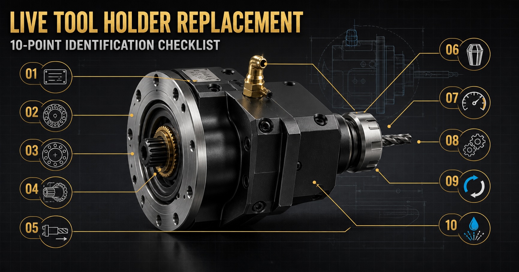
The 10-point checklist for identifying a replacement live tool holder
1. CNC machine brand and full model
Provide the brand and complete model — e.g. TSUGAMI B0205, STAR SR-20R, Citizen Cincom L20, Miyano BNJ-42, Doosan/DN Solutions Puma series. The same brand may use different turrets, drive systems, and mounting dimensions, so the brand name alone is usually not enough. If the nameplate shows a manufacturing year, serial, or type number, please include it.2. Turret brand, model and station
Confirm which turret and station the holder mounts to: main or sub turret, upper or lower turret, front or back-working position, face or side operation, and BMT, VDI, BOT, or a machine-specific turret. Photograph the turret front, side, and mounting position; if the turret or drive unit has a nameplate, provide a clear photo.3. Existing holder brand, model and serial
Check the holder body for brand, model, part number, serial, maximum speed, rotation-direction marking, coolant pressure, and reduction/step-up ratio. Photograph the complete nameplate — not a partial or blurry shot. The original part number is important, but some numbers are revised, discontinued, or coded differently by market, so it shouldn't be the sole basis for a decision.4. Turret mounting interface
Common interfaces: VDI (cylindrical-shank, e.g. VDI 20/25/30/40), BMT (base-type bolted to the turret face), BOT (a specific bolt-on form), and machine-specific interfaces common on Swiss-type and Japanese machines. For BMT/BOT, confirm the locating-face dimensions, bolt-hole count and pitch, key/pin position, holder center height, and mounting orientation; for VDI, confirm shank diameter, serration form, and locating orientation. Writing only "BMT40" may not be enough — different turret makers can still use different drive positions or mounting details.5. Drive coupling shape and dimensions
The live tool must engage the turret's internal drive coupling correctly. Common forms: Square, Hex, Polygon, Spline, Round/keyed, or a machine-specific coupling. Photograph the coupling face and measure across-flats, outer diameter, length, key width, spline tooth count, and the drive-center distance relative to the mounting face. A matching interface does not guarantee a compatible coupling; the wrong coupling may fail to engage, or cause backlash, noise, heat, or vibration in operation.6. Machining direction
Confirm which type you need: Axial (end-working), Radial (side), Angular, adjustable-angle, offset, or a speeder (step-up). For angular holders, indicate the required angle (e.g. 30°, 45°, 90°). Providing the actual operation position and a workpiece drawing helps the supplier confirm tool projection direction, interference range, and turret clearance.7. Tool clamping method and size
Confirm the output-end clamping: ER collet (ER11/16/20/25/32, etc.), Weldon side-lock, hydraulic chuck, drill chuck, tapping collet, face mill arbor, saw blade arbor, or a special interface. Also provide tool diameter, maximum clamping diameter, tool projection length, required torque, and whether axial floating or rigid tapping is needed.8. Maximum speed, torque and gear ratio
Provide turret drive speed, target tool speed, maximum allowable speed, required torque, continuous or intermittent operation, and the gear ratio (1:1, reduction, or step-up). Micro-drilling and engraving may need a speeder; large-diameter drilling, milling, and heavy cutting weigh torque and rigidity more. Don't compare peak speed alone — bearing configuration, gear precision, lubrication, temperature rise, and allowable load all affect real service life.9. Rotation direction
Confirm the viewing direction used to judge rotation, and indicate CW/CCW, whether both directions are possible, and the turret-input and tool-output directions. A gear train can reverse rotation between input and output, so you can't infer tool rotation from the turret motor alone. The safest options are the arrow marking on the original holder, or a low-speed jog video taken while following the machine's safety rules.10. Coolant method and pressure
Confirm whether the holder needs external coolant, internal (center) coolant, through-tool coolant, or no coolant channel. For internal coolant, also provide the inlet position, connector type, working and maximum pressure, flow requirement, and cutting-fluid type. A standard low-pressure external-coolant holder cannot be assumed to withstand high-pressure center coolant; exceeding the design pressure can cause seal failure, leaks, or bearing contamination.Recommended photos and dimensions
To speed up confirmation, provide in one batch: the full machine and its nameplate; turret front and side; the existing holder's full view, nameplate, and part number; the mounting interface; the drive coupling face; the tool-clamping end; the coolant inlet; and dimension-measurement photos. Placing a caliper or scale in the photo helps a first estimate, but formal selection should rely on drawings and actual measured values. Measure at least: overall holder length, mounting-face width and height, tool center height, bolt-hole diameter and pitch, key size, coupling dimensions, output-end spec, maximum clamping diameter, and clearance to adjacent stations. State the unit (mm or inch) and whether each value is measured, from a drawing, or estimated.Common inquiry mistakes
- Brand only: "for Citizen" isn't enough — one brand can use many turrets and interfaces.
- A single front photo: it usually hides the mounting base, drive coupling, key, and coolant inlet.
- Comparing appearance only: a similar shape doesn't mean the same center height, gear ratio, rotation, interface, and coolant channel.
- No rotation direction or real cutting conditions: tool diameter, material, speed, and depth of cut affect required torque, rigidity, and coolant capacity.
Need help identifying a replacement live tool holder?
Z&Z STROTEC supplies and sources live tool holders for CNC lathes and Swiss-type machines. Send us the machine model, existing holder details, interface photos, and machining requirements, and we'll help evaluate compatibility and confirm the information needed for a quotation. All replacement and compatibility decisions should be based on the machine maker's data, turret specifications, formal drawings, and the acceptance criteria agreed by both sides.
Live Tool Holder Troubleshooting: Causes of Overheating, Noise, Runout and Coolant Leakage
Before working through the ten identification points, it is worth confirming that the holder is actually the fault. Runout at the tool tip can come from the tool, the collet, the mounting face or the turret just as easily as from the output shaft — and a holder condemned on one measurement is an avoidable purchase.
Clean the clamping system, fit a known-good tool and collet, measure near the clamp and then at the tip, then measure the output end with no tool fitted. If several holders show the same reading in the same station, the turret or the machine geometry is the more likely cause.
Professional repair of a precision holder normally covers bearings, drive train, internal coolant passages and drive-coupling adjustment, with noise, temperature and accuracy testing afterwards. The column sets out the conditions that make a holder a repair candidate, and the ones that mean stop running it now.
動力刀座損壞、精度下降或原廠型號停產時,不能只憑外觀或機台品牌選購替代品。即使兩把刀座看起來相似,只要刀塔接口、驅動接頭、旋轉方向或冷卻方式不同,就可能無法安裝,甚至造成干涉、漏水、異常震動或刀塔損壞。
向供應商詢價前,請準備以下 10 項資料。資料越完整,越能縮短確認時間並降低選錯規格的風險。
動力刀座更換/詢價的 10 項辨識清單
1. CNC 機台品牌與完整型號
請提供機台品牌及完整型號,例如 TSUGAMI B0205、STAR SR-20R、Citizen Cincom L20、Miyano BNJ-42、Doosan/DN Solutions Puma 系列。同一品牌可能使用不同刀塔、驅動系統與安裝尺寸,只提供品牌名稱通常不足以確認刀座。若銘牌上有製造年份、序號或型式編號,建議一併提供。2. 刀塔品牌、型號與工位
確認動力刀座安裝在哪一座刀塔及哪一個工位:主刀塔或副刀塔、上刀塔或下刀塔、前側或背側工位、端面或側面加工位,以及 BMT、VDI、BOT 或機台專用刀塔。請拍攝刀塔正面、側面與刀座安裝位置;若刀塔或驅動單元有銘牌,也請提供清晰照片。3. 原刀座的品牌、型號與序號
檢查刀座本體上的品牌、型號、料號、序號、最大轉速、旋向標示、冷卻壓力、減速比或增速比。請拍攝完整銘牌,不要只傳局部或模糊照片。原廠料號非常重要,但部分料號可能已改版、停產,或因不同市場而使用不同編碼,因此不能單獨作為判定依據。4. 刀塔安裝接口
常見接口:VDI(圓柱柄接口,如 VDI 20/25/30/40)、BMT(以螺栓固定於刀塔面的底座式接口)、BOT(特定螺栓固定形式),以及常見於走心式車床與日系機台的機台專用接口。BMT/BOT 需確認定位面尺寸、螺栓孔數量與孔距、定位鍵或定位銷位置、刀座中心高、安裝方向;VDI 則確認柄徑、齒形與定位方向。僅寫「BMT40」不一定足夠,不同刀塔製造商仍可能採用不同的驅動位置或安裝細節。5. 驅動接頭的形狀與尺寸
動力刀座必須和刀塔內部的驅動接頭正確咬合。常見形式:方形(Square)、六角(Hex)、多邊形(Polygon)、花鍵(Spline)、圓軸加鍵槽(Round/keyed)、機台專用聯軸器。請拍攝驅動接頭正面,並量測對邊尺寸、外徑、長度、鍵寬、花鍵齒數、驅動中心相對安裝面的距離。接口能安裝不代表驅動接頭一定相容;錯誤接頭可能無法咬合,也可能在運轉時造成背隙、異音、發熱或震動。6. 刀座加工方向
請確認需要哪一種:軸向/端面(Axial)、徑向/側面(Radial)、角度型(Angular)、可調角度、偏置型(Offset)、增速刀座(Speeder)。若是角度型,請標示所需角度(如 30°、45°、90°)。最好提供實際加工位置與工件圖,讓供應商確認刀具伸出方向、干涉範圍與刀塔空間。7. 刀具夾持方式與尺寸
請確認輸出端夾持方式:ER 筒夾(ER11/16/20/25/32 等)、Weldon side-lock、油壓夾頭、鑽夾頭、攻牙筒夾、面銑刀桿、鋸片刀桿或特殊接口。同時提供刀具直徑、最大夾持直徑、刀具伸出長度、加工所需扭矩,以及是否需要軸向浮動或剛性攻牙。8. 最大轉速、扭矩與傳動比
請提供刀塔驅動轉速、刀具目標轉速、最大允許轉速、所需扭矩、連續或間歇運轉,以及 1:1/減速/增速傳動比。微孔鑽削與雕刻可能需要增速刀座;大徑鑽孔、銑削或重切削則更重視扭矩與剛性。不要只比較最高轉速,軸承配置、齒輪精度、潤滑方式、溫升與允許負載同樣影響實際使用壽命。9. 旋轉方向
請確認從哪一個觀察方向判定旋向,並標示 CW(順時針)/CCW(逆時針)、可否正反轉、刀塔輸入方向與刀具輸出方向。齒輪組可能改變輸入與輸出的旋轉方向,因此不能只根據刀塔馬達方向推測刀具旋向。最安全的方式是提供原刀座上的箭頭標示,或在遵守機台安全規範下拍攝低速點動影片。10. 冷卻方式與壓力
請確認需要外部冷卻(External)、中心/內部出水(Internal)、刀具中心出水(through-tool)或不需冷卻通道。若需內冷,請提供冷卻液入口位置、接頭形式、工作壓力、最大壓力、流量需求與切削液種類。一般低壓外冷刀座不一定能承受高壓中心出水,使用超過設計壓力的冷卻系統可能造成密封失效、漏水或軸承污染。建議提供的照片與尺寸
為加快確認速度,建議一次提供:機台完整外觀與銘牌、刀塔正面與側面、原刀座完整外觀/銘牌/料號、刀塔安裝接口、驅動接頭正面、刀具夾持端、冷卻液入口、尺寸量測照片。照片中放入游標卡尺或比例尺有助於初步判斷,但正式選型仍應以圖面及實際量測值為準。至少量測:刀座總長、安裝面寬度與高度、刀具中心高、螺栓孔徑與孔距、定位鍵尺寸、驅動接頭尺寸、輸出端規格、最大夾持直徑、與相鄰工位的可用空間。請標示單位(mm 或 inch),並說明為實際量測值、圖面值或估計值。常見的詢價錯誤
- 只提供機台品牌:同一品牌可能搭配多種刀塔及驅動接口,僅寫「Citizen 用」不足以完成選型。
- 只提供一張正面照片:通常看不到安裝底面、驅動接頭、定位鍵及冷卻入口。
- 只比較外觀:外形相似不代表中心高、齒輪比、旋向、接口和冷卻通道相同。
- 未確認旋向或實際加工條件:刀具直徑、材質、轉速與切深會影響所需扭矩、剛性及冷卻能力。
需要協助辨識替換用動力刀座?
Z&Z STROTEC 萬洋國際供應並協助尋源 CNC 車床與走心式機台的動力刀座。請提供機台型號、原刀座資訊、接口照片與加工需求,我們會協助評估相容性並確認詢價所需項目。所有替換與相容性判定應以機台製造商資料、刀塔規格、正式圖面及雙方確認的允收條件為準。
動力刀座故障診斷:過熱、異音、偏擺與漏水的原因及處理方式
在逐項對照這十點辨識資訊之前,值得先確認:真正故障的是不是刀座本身。刀尖偏擺可能來自刀具、筒夾、安裝面或刀塔,機率不見得低於輸出軸——只憑一次量測就判定刀座報廢,是可以避免的採購。
先清潔夾持系統,換上已知正常的刀具與筒夾,量測靠近夾持端再量刀尖,最後不裝刀具量測輸出端。若多支刀座在同一刀位都出現相同讀數,問題更可能在刀塔或機台幾何精度。
精密刀座的專業維修通常涵蓋軸承、傳動系統、內部冷卻通道與驅動接頭調整,並在組裝後進行噪音、溫度與精度測試。專欄整理了哪些狀況適合送修,以及哪些狀況必須立即停止運轉。
라이브 툴 홀더가 손상되거나 정밀도가 떨어지거나 원 모델이 단종되었을 때, 외관이나 기계 브랜드만으로 대체품을 고르면 안 됩니다. 두 홀더가 비슷해 보여도 터렛 인터페이스, 구동 커플링, 회전 방향 또는 냉각 방식이 다르면 장착이 안 되거나 간섭·누수·이상 진동·터렛 손상으로 이어질 수 있습니다.
견적을 요청하기 전에 아래 10가지 정보를 준비해 주세요. 자료가 완전할수록 확인 시간이 짧아지고 규격 오선정 위험이 줄어듭니다.
라이브 툴 홀더 교체·견적을 위한 10항목 식별 체크리스트
1. CNC 기계 브랜드와 전체 모델명
브랜드와 전체 모델명을 알려주세요 (예: TSUGAMI B0205, STAR SR-20R, Citizen Cincom L20, Miyano BNJ-42, Doosan/DN Solutions Puma 시리즈). 같은 브랜드라도 터렛·구동 시스템·장착 치수가 다를 수 있어 브랜드명만으로는 부족합니다. 명판에 제조 연도·시리얼·형식 번호가 있으면 함께 제공해 주세요.2. 터렛 브랜드·모델·스테이션
어느 터렛의 어느 스테이션에 장착되는지 확인해 주세요: 메인/서브 터렛, 상/하 터렛, 정면/배면 가공 위치, 그리고 BMT·VDI·BOT 또는 기계 전용 형식. 터렛 정면·측면·장착 위치를 촬영하고 명판이 있으면 선명한 사진을 제공해 주세요.3. 기존 홀더의 브랜드·모델·시리얼
홀더 본체의 브랜드, 모델, 파트 번호, 시리얼, 최대 회전수, 회전 방향 표시, 냉각 압력, 감속/증속비를 확인해 주세요. 명판 전체를 선명하게 촬영해 주세요. 원 파트 번호는 매우 중요하지만, 개정·단종되었거나 시장별로 다르게 표기될 수 있어 단독 판단 근거로는 부족합니다.4. 터렛 장착 인터페이스
일반적인 인터페이스: VDI(원통형 섕크, VDI 20/25/30/40 등), BMT(볼트로 터렛 면에 고정하는 베이스형), BOT, 그리고 주로 스위스형·일본계 기계의 전용 인터페이스. BMT/BOT는 위치 결정면 치수, 볼트 구멍 수·피치, 키/핀 위치, 중심 높이, 장착 방향을 확인해야 합니다. "BMT40"이라고만 적는 것으로는 부족할 수 있습니다 — 제조사에 따라 구동 위치나 세부가 다를 수 있기 때문입니다.5. 구동 커플링의 형상과 치수
라이브 툴은 터렛 내부 구동 커플링과 정확히 맞물려야 합니다. 형식: 사각(Square), 육각(Hex), 다각형(Polygon), 스플라인(Spline), 원형+키(Round/keyed), 전용 커플링. 커플링 정면을 촬영하고 대변 치수, 외경, 길이, 키 폭, 스플라인 잇수, 장착면 대비 구동 중심 거리를 측정해 주세요. 인터페이스가 맞아도 커플링이 호환된다는 보장은 없으며, 잘못된 커플링은 백래시·소음·발열·진동을 유발할 수 있습니다.6. 가공 방향
필요한 유형: 액시얼(축방향/정면), 레이디얼(측면), 앵귤러(각도형), 각도 조절형, 오프셋형, 스피더(증속형). 앵귤러라면 필요한 각도(30°·45°·90° 등)를 표시하고, 실제 가공 위치와 공작물 도면을 제공하면 공구 돌출 방향·간섭 범위 확인에 도움이 됩니다.7. 공구 클램핑 방식과 치수
출력단 클램핑: ER 콜릿(ER11/16/20/25/32 등), Weldon 사이드락, 유압 척, 드릴 척, 태핑 콜릿, 페이스밀 아버, 톱날 아버 등. 함께 제공: 공구 직경, 최대 클램핑 직경, 공구 돌출 길이, 필요 토크, 축방향 플로팅/강성 태핑 여부.8. 최대 회전수·토크·기어비
필요 사양: 터렛 구동 회전수, 공구 목표 회전수, 최대 허용 회전수, 필요 토크, 연속/단속 운전, 기어비(1:1·감속·증속). 미세 드릴링·조각은 증속 홀더가, 대경 드릴링·중절삭은 토크와 강성이 중요합니다. 최고 회전수만 비교하지 말고 베어링 구성·기어 정밀도·윤활·온도 상승·허용 부하도 함께 고려하세요.9. 회전 방향
어느 방향에서 본 기준인지 명시하고 CW(시계)/CCW(반시계), 정·역회전 가능 여부, 터렛 입력·공구 출력 방향을 표시해 주세요. 기어 조합이 입력과 출력의 방향을 바꿀 수 있으므로 모터 방향만으로 추정하면 안 됩니다. 기존 홀더의 화살표 표시를 제공하거나, 안전 규정을 지킨 상태에서 저속 조그 영상을 촬영하는 것이 가장 확실합니다.10. 냉각 방식과 압력
필요 유형: 외부 냉각, 내부(중심) 냉각, 공구 중심 관통(through-tool), 냉각 불필요. 내부 냉각이면 입구 위치, 커넥터 형식, 사용/최대 압력, 유량, 절삭유 종류를 제공해 주세요. 일반 저압 외부 냉각 홀더가 고압 중심 출수를 견딘다는 보장은 없으며, 설계 압력 초과는 실링 손상·누수·베어링 오염으로 이어질 수 있습니다.권장 사진 · 치수
가능하면 한 번에 제공해 주세요: 기계 전경·명판, 터렛 정면·측면, 기존 홀더 전경·명판·파트번호, 장착 인터페이스, 구동 커플링 정면, 공구 클램핑단, 냉각 입구, 치수 측정 사진. 사진에 캘리퍼나 스케일을 함께 두면 초기 판단에 도움이 되지만, 정식 선정은 도면과 실측값을 기준으로 합니다. 최소 측정 항목: 홀더 전장, 장착면 폭·높이, 공구 중심 높이, 볼트 구멍 직경·피치, 키 치수, 커플링 치수, 출력단 규격, 최대 클램핑 직경, 인접 스테이션과의 여유 공간. 단위(mm/inch)와 실측/도면/추정 여부를 표기해 주세요.흔한 견적 실수
- 브랜드만 제공: "Citizen용"만으로는 선정이 불가능합니다 — 같은 브랜드도 여러 터렛·인터페이스를 씁니다.
- 정면 사진 한 장만 제공: 장착면·구동 커플링·키·냉각 입구가 보이지 않습니다.
- 외관만 비교: 닮았다고 중심 높이·기어비·회전 방향·인터페이스가 같지는 않습니다.
- 회전 방향 미확인 / 실제 가공 조건 미제공: 공구 직경·소재·회전수·절입은 필요 토크·강성·냉각 능력에 영향을 줍니다.
교체용 라이브 툴 홀더 식별에 도움이 필요하신가요?
Z&Z STROTEC는 CNC 선반 및 스위스형 기계용 라이브 툴 홀더를 공급·소싱합니다. 기계 모델, 기존 홀더 정보, 인터페이스 사진, 가공 요구사항을 보내주시면 호환성을 함께 검토하고 견적에 필요한 항목을 확인해 드립니다. 모든 교체·호환 판정은 기계 제조사 자료, 터렛 규격, 정식 도면 및 양측이 합의한 허용 기준을 기준으로 합니다.
라이브 툴 홀더 고장 진단: 과열·이음·런아웃·절삭유 누유의 원인과 대처
10가지 식별 항목을 확인하기 전에, 실제로 고장 난 것이 홀더가 맞는지 먼저 확인할 가치가 있습니다. 공구 선단의 런아웃은 출력축만이 아니라 공구·콜릿·장착면·터렛에서도 그만큼 자주 나옵니다. 한 번의 측정으로 홀더를 폐기 판정하는 것은 피할 수 있는 지출입니다.
클램핑계를 청소하고, 정상으로 확인된 공구와 콜릿으로 바꾼 뒤, 클램핑부 근처와 공구 선단을 차례로 측정하고, 마지막으로 공구를 빼고 출력단을 측정합니다. 여러 홀더가 같은 공구 위치에서 같은 값을 보이면 터렛이나 기계 기하 정밀도가 더 유력한 원인입니다.
정밀 홀더의 전문 수리는 보통 베어링, 구동 계통, 내부 절삭유 통로, 구동 커플링 조정을 포함하고 조립 후 소음·온도·정밀도 시험을 거칩니다. 칼럼에서는 수리 대상이 되는 조건과 즉시 운전을 멈춰야 하는 조건을 정리했습니다.
장비 모델명, 부품 번호 또는 현장 사진을 보내주시면 공급 가능 여부와 가격을 회신드립니다.
Multi-brand selection rather than one factory, spec and compatibility checks in writing, a test cut and inspection at the plant before the machine ships, export documentation, and the same part number still available years later. Installation and after-sales in Korea, Brazil, Switzerland and Argentina run through local agents; for other markets we supply parts and components.
不綁單一工廠的多品牌選型、白紙黑字的規格與相容性確認、出貨前在工廠端試車驗機、出口文件,以及數年後仍拿得到的同一料號。韓國、巴西、瑞士、阿根廷的安裝與售後由在地服務商執行,其他市場我們供應零件與零組件。
단일 공장에 묶이지 않는 다중 브랜드 선정, 문서로 남기는 사양·호환성 확인, 선적 전 공장 시운전과 검사, 수출 서류, 그리고 수년 뒤에도 확보 가능한 동일 품번. 한국·브라질·스위스·아르헨티나의 설치와 애프터서비스는 현지 대리점이 담당하며, 그 외 시장에는 부품을 공급합니다.